多字节串口收发IP设计(三)串口发送模块设计及仿真(含源码)
串口发送模块的设计比较简单,按照串口的发送时序按位将数据发送出去即可。
本模块比较特殊的是增加了奇偶校验的计算,并支持奇偶校验的设置。
模块接口
信号名 | 位宽 | 说明 |
I_clk | 1 | 模块时钟 |
I_rst | 1 | 模块复位,高电平有效 |
I_uart_baud_cnt | 16 | 波特率计数器,计数单bit时钟数 |
I_uart_check | 2 | 校验位设置:0-无校验,1-奇校验,2-偶校验 |
I_user_tx_data | 8 | 用户发送的数据 |
I_user_tx_valid | 1 | 用户发送数据有效,高电平有效 |
O_user_tx_ready | 1 | 模块发送准备好,高电平有效 |
O_uart_tx | 1 | 串行数据发送 |
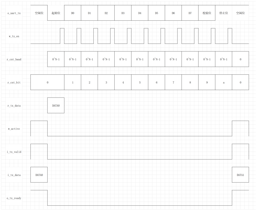
串口发送时序
源代码
`timescale 1ns / 1psmodule UART_tx #(parameter   C_DATA_WIDTH = 8            ,   //7,8,9,10parameter   C_STOP_WIDTH = 1               //1,2
)(input   wire                            i_clk               ,input   wire                            i_rst               ,input   wire    [15:0]                  i_uart_baud_cnt     ,input   wire    [ 1:0]                  i_uart_check        , //0-no,1-odd,2-eveninput   wire    [C_DATA_WIDTH-1:0]      i_user_tx_data      ,input   wire                            i_user_tx_valid     ,output  reg                             o_user_tx_ready     ,output  reg                             o_uart_tx           );////////////////////////////////////////////////////////////////////
//parameter define
localparam      C_DATA_LEN = 2 + C_DATA_WIDTH + C_STOP_WIDTH ; //start+data+check+stop//reg define
reg     [15:0]                  r_cnt_bit                       ;
reg     [15:0]                  r_cnt_baud                      ;
reg     [C_DATA_WIDTH-1:0]      r_tx_data                       ;
reg                             r_tx_check                      ;
//wire define
wire                            w_active                        ;
wire                            w_tx_en                         ;////////////////////////////////////////////////////////////////////assign w_active = i_user_tx_valid & o_user_tx_ready ;
assign w_tx_en = (r_cnt_baud == i_uart_baud_cnt - 1 );////////////////////////////////////////////////////////////////////always @(posedge i_clk) beginif (i_rst)r_cnt_baud <= 0 ;else if (!o_user_tx_ready && r_cnt_baud < i_uart_baud_cnt - 1)r_cnt_baud <= r_cnt_baud + 1 ;else r_cnt_baud <= 0 ;
endalways @(posedge i_clk ) beginif (i_rst)o_user_tx_ready <= 1 ;else if (w_active)o_user_tx_ready <= 0 ;else if ((r_cnt_bit == C_DATA_LEN - 2) && (i_uart_check == 0) && (r_cnt_baud == i_uart_baud_cnt - 2 ))o_user_tx_ready <= 1 ;else if ((r_cnt_bit == C_DATA_LEN - 1) && (i_uart_check > 0) && (r_cnt_baud == i_uart_baud_cnt - 2 ))o_user_tx_ready <= 1 ;
endalways @(posedge i_clk ) beginif (i_rst)r_cnt_bit <= 0 ;else if ((r_cnt_bit == C_DATA_LEN - 2) && (i_uart_check == 0) && w_tx_en)r_cnt_bit <= 0 ;else if ((r_cnt_bit == C_DATA_LEN - 1) && (i_uart_check > 0) && w_tx_en)r_cnt_bit <= 0 ;else if (!o_user_tx_ready && w_tx_en)r_cnt_bit <= r_cnt_bit + 1 ;
endalways @(posedge i_clk ) beginif (i_rst)r_tx_data <= 0 ;else if (w_active)r_tx_data <= i_user_tx_data ;else if (!o_user_tx_ready && w_tx_en)r_tx_data <= r_tx_data >> 1 ;
endalways @(posedge i_clk ) beginif (i_rst) o_uart_tx <= 1 ; // idleelse if (w_active)o_uart_tx <= 0 ; //send startelse if ((r_cnt_bit == C_DATA_LEN - 3) && (i_uart_check > 0) && w_tx_en) o_uart_tx <= i_uart_check == 1 ? ~r_tx_check : r_tx_check ; //send checkelse if ((r_cnt_bit == C_DATA_LEN - 3) && (i_uart_check == 0) && w_tx_en) o_uart_tx <= 1 ; //send stopelse if ((r_cnt_bit >= C_DATA_LEN - 2) && (i_uart_check > 0) && w_tx_en) o_uart_tx <= 1 ; //send stopelse if (!o_user_tx_ready && w_tx_en)o_uart_tx <= r_tx_data[0] ; //send dataelse if (o_user_tx_ready) o_uart_tx <= 1 ; // idle
endalways @(posedge i_clk) beginif (i_rst)r_tx_check <= 0 ;else if ((r_cnt_bit == C_DATA_LEN - 3 )&& w_tx_en) r_tx_check <= 0 ;else if (!o_user_tx_ready && w_tx_en)r_tx_check <= r_tx_check ^ r_tx_data[0] ;
endendmodule
仿真代码
`timescale 1ns / 1psmodule tb_UART( );
reg                            i_clk               ;
reg                            i_rst               ;
reg    [31:0]                  i_uart_baud_cnt     ;
reg    [ 1:0]                  i_uart_check        ; //0-no,1-odd,2-even
reg    [ 7:0]                   i_user_tx_data      ;
reg                            i_user_tx_valid     ;
wire                             o_user_tx_ready     ;
wire                             o_uart_tx          ;wire w_active = i_user_tx_valid & o_user_tx_ready ;initial begini_clk = 0 ;i_rst = 1 ;i_uart_check = 2 ;i_uart_baud_cnt = 4 ;#100;@(posedge i_clk) i_rst = 0 ;
endalways #5 i_clk = ~i_clk ;always @(posedge i_clk) beginif (i_rst)i_user_tx_data <= 0 ;else if (w_active)i_user_tx_data <= i_user_tx_data + 1 ;
endalways @(posedge i_clk) beginif (i_rst)i_user_tx_valid <= 0 ;else if (w_active)i_user_tx_valid <= 0 ; else if (o_user_tx_ready)i_user_tx_valid <= 1 ;
endUART_tx u_UART_tx(.i_clk           (i_clk           ),.i_rst           (i_rst           ),.i_uart_baud_cnt (i_uart_baud_cnt ),.i_uart_check    (i_uart_check    ),.i_user_tx_data  (i_user_tx_data  ),.i_user_tx_valid (i_user_tx_valid ),.o_user_tx_ready (o_user_tx_ready ),.o_uart_tx       (o_uart_tx       )
);endmodule
仿真结果
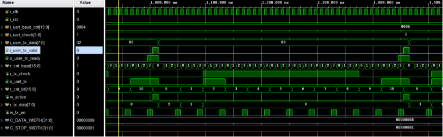
无校验
将i_uart_check信号赋值为0,表示无校验,则数据的长度为:起始位+数据位+停止位=10。
通过仿真结果可以看出,发送时序符合串口发送格式。
R_cnt_bit为0时对应起始位,为1~8时对应数据位,为9时对应停止位。
停止位结束后,紧跟着空闲位,在i_user_tx_valid与o_user_tx_ready同时有效时,触发下一次数据的发送。
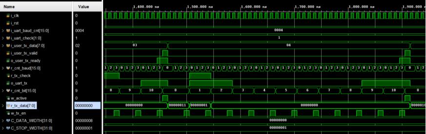
奇校验
将i_uart_check信号赋值为1,表示奇校验,则数据的长度为:起始位+数据位+校验位+停止位=11。
发送数据为2时,其二进制为00000010,数据位有1个1,是奇数,则校验位就为0,r_cnt_bit为9时对应校验位,符合预期。

发送数据为3时,其二进制为00000011,数据位有2个1,是偶数,则校验位就为1,r_cnt_bit为9时对应校验位,符合预期。
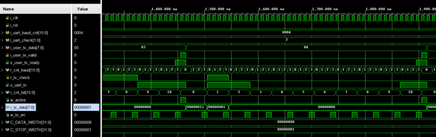
偶校验
将i_uart_check信号赋值为2,表示偶校验,则数据的长度为:起始位+数据位+校验位+停止位=11。
发送数据为2时,其二进制为00000010,数据位有1个1,是奇数,则校验位就为1,r_cnt_bit为9时对应校验位,符合预期。
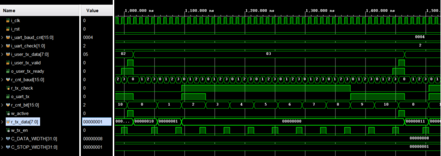
发送数据为3时,其二进制为00000011,数据位有2个1,是偶数,则校验位就为0,r_cnt_bit为9时对应校验位,符合预期。