路由交换技术-思科拓扑搭建
配置流程
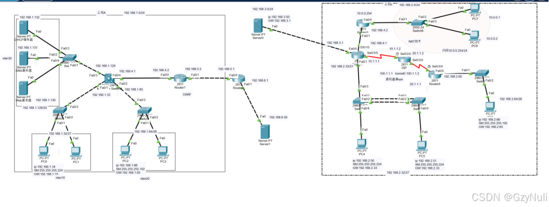
1.搭建网络拓扑图。
2.规划配置IP地址,内网配置为192.168.1.0和192.168.2.0网段。
3.划分vlan10,vlan20,vlan30。
4.配置静态、动态路由。配置路由器Router7,使内外网互通。
5.配置链路聚合。通过链路聚合技术,将交换机的两条链路捆绑成一条,提高链路带宽。
6.配置静态NAT。实现私有地址转公有地址。
7.配置ACL,实现访问控制。
8.配置RIP2协议。在三层交换机上配置,,实现网段互通。
9.配置OSRF协议。在R1和R2上配置OSRF协议,实现网络连通。
10.配置VPN。配置R7和R9,建立GRE隧道。
11.服务器配置(WEB,DHCP,DNS服务器),实现对服务器的服务功能测试。
一、 *IP地址表*
表1-1 路由器的IP地址规划表
| 名称 | 接口 | IP地址 | 子网掩码 | 默认网关 |
|---|---|---|---|---|
| 三层交换机 | F0/1 | 192.168.1.33 | 255.255.255.224 | / |
| F0/2 | 192.168.1.65 | 255.255.255.192 | / | |
| F0/3 | 192.168.1.129 | 255.255.255.128 | / | |
| F0/4 | 192.168.4.1 | 255.255.255.0 | / | |
| 7Router0 | F0/0 | 10.0.0.254 | 255.255.255.0 | / |
| F0/1 | 192.168.4.2 | 255.255.255.0 | / | |
| Router1 | F0/0 | 192.168.4.2 | 255.255.255.0 | / |
| F0/1 | 192.168.5.2 | 255.255.255.0 | / | |
| Router2 | F0/0 | 192.168.5.1 | 255.255.255.0 | / |
| F0/1 | 192.168.6.1 | 255.255.255.0 | / | |
| Router7 | F0/0 | 192.168.3.1 | 255.255.255.0 | / |
| F0/1 | 192.168.2.33 | 255.255.255.224 | / | |
| Se0/3/0 | 10.1.1.1 | 255.255.255.0 | / | |
| Eth1/0 | 192.168.4.1 | 255.255.255.0 | / | |
| ISP | Se0/2/0 | 10.1.1.2 | 255.255.255.0 | / |
| Se0/3/0 | 20.1.1.2 | 255.255.255.0 | / | |
| Router9 | Se0/3/0 | 20.1.1.1 | 255.255.255.0 | / |
| F0/0 | 192.168.2.65 | 255.255.255.192 | / |
表1-2主机的IP地址规划表
| 名称 | 接口 | IP地址 | 子网掩码 | 默认网关 |
|---|---|---|---|---|
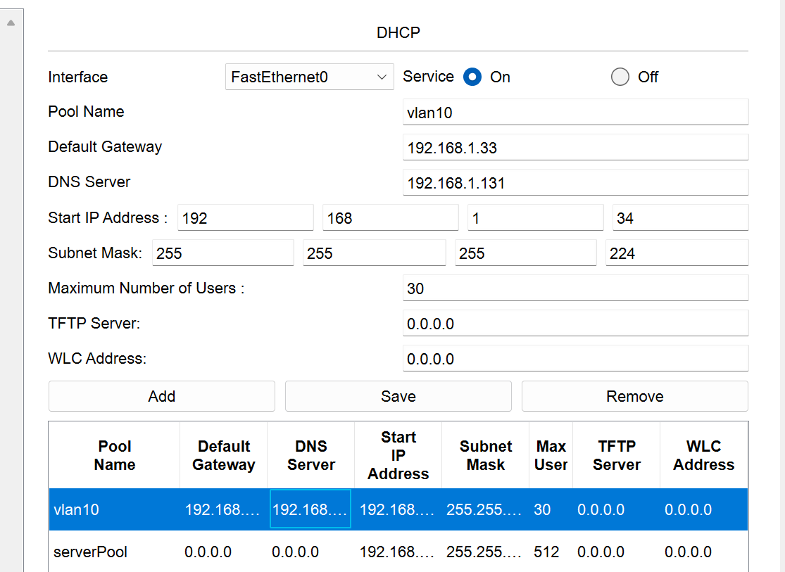
| PC0 | Fa0 | 192.168.1.34 | 255.255.255.224 | 192.168.1.33 |
| PC1 | Fa0 | DHCP自动分配 | 255.255.255.224 | 192.168.1.33 |
| PC2 | Fa0 | 192.168.1.66 | 255.255.255.192 | 192.168.51.1 |
| PC3 | Fa0 | DHCP自动分配 | 255.255.255.192 | 192.168.51.1 |
| PC4 | Fa0 | 192.168.2.50 | 255.255.255.224 | 192.168.2.33 |
| 名称 | 接口 | IP地址 | 子网掩码 | 默认网关 |
| PC5 | Fa0 | 192.168.2.51 | 255.255.255.224 | 192.168.2.33 |
| PC6 | Fa0 | 192.168.2.66 | 255.255.255.192 | 192.168.2.65 |
| PC7 | Fa0 | 10.0.0.1 | 255.255.255.0 | 10.0.0.254 |
| PC8 | Fa0 | 10.0.0.2 | 255.255.255.0 | 10.0.0.254 |
表1-3服务器的IP地址规划表
| 名称 | 接口 | IP地址 | 子网掩码 | 默认网关 |
|---|---|---|---|---|
| DNS服务器 | Fa0 | 192.168.1.131 | 255.255.255.128 | 192.168.1.128 |
| DHCP服务器 | Fa0 | 192.168.1.132 | 255.255.255.128 | 192.168.1.128 |
| HTTP服务器 | Fa0 | 192.168.1.130 | 255.255.255.128 | 192.168.1.128 |
| Server0 | Fa0 | 192.168.3.50 | 255.255.255.0 | 192.168.3.1 |
| Server1 | Fa0 | 192.168.6.50 | 255.255.255.0 | 192.168.6.1 |
二、 *VLAN和端口号分配表*
表2 VLAN和端口号分配表
| *设备* | *用途* | *端口号* | *VLAN号* |
|---|---|---|---|
| 三层交换机(S3560) | 办公区 | F0/1 | VLAN10 |
| 财政区 | F0/2 | VLAN20 | |
| 服务器区 | F0/3 | VLAN30 |
三、 *路由规划表*
表3 路由规划表
| 设备 | 路由方式 | 目的地址 | 下一跳 | 宣告网段 |
|---|---|---|---|---|
| Switch0 | Static | - | - | - |
| - | - | - | ||
| RIP 2 | - | - | 192.168.1.0 | |
| Router7 | Static | 0.0.0.0/0 | 10.1.1.2 | - |
| RIP 2 | - | - | 100.0.0.0 | |
| - | - | 192.168.3.0 | ||
| Router9 | Static | 0.0.0.0/0 | 20.1.1.2 | - |
| RIP2 | - | - | 100.0.0.0 | |
| ISP | Static | 0.0.0.0/0 | 10.1.1.1 | - |
| 0.0.0.0/0 | 20.1.1.1 | - | ||
| RIP 2 | - | - |
技术实现
划分vlan
| vlan | 网段 |
|---|---|
| vlan10 | 192.168.1.32/27 |
| vlan20 | 192.168.1.64/26 |
| vlan30 | 192.168.1.128/25 |
1.分别在三个二层交换机创建vlan10,vlan20,vlan30
Switch>enable
Switch#conf t
Enter configuration commands, one per line.  End with CNTL/Z.
Switch(config)#vlan 10
Switch(config-vlan)#name vlan10
Switch(config-vlan)#exit
Switch(config)#
2.vlan端口分配
Switch(config)#interface f0/1
Switch(config-if)#switchport access vlan 10
Switch(config-if)#exit
Switch(config)#interface f0/2
Switch(config-if)#switchport access vlan 10
Switch(config-if)#exit
其他交换机同理
3.二层交换机端口分配
设置交换机互联的端口模式为Trunk
Switch(config)#interface f0/3
Switch(config-if)#switchport mode trunkSwitch(config-if)#
%LINEPROTO-5-UPDOWN: Line protocol on Interface FastEthernet0/3, changed state to down%LINEPROTO-5-UPDOWN: Line protocol on Interface FastEthernet0/3, changed state to upSwitch(config-if)#exit
4.三层交换机接口配置
创建vlan
Switch>enable
Switch#conf t
Enter configuration commands, one per line.  End with CNTL/Z.
Switch(config)#
Switch(config)#
Switch(config)#vlan 10
Switch(config-vlan)#name vlan10
Switch(config-vlan)#exit
Switch(config)#vlan 20
Switch(config-vlan)#name vlan20
Switch(config-vlan)#exit
Switch(config)#vlan 30
Switch(config-vlan)#name vlan30
Switch(config-vlan)#exit
5.交换机端口分配:配置Trunk封装为802.1q协议,设置为Trunk模式
Switch(config)#vlan 10
Switch(config-vlan)#name vlan10
Switch(config-vlan)#vlan 20
Switch(config-vlan)#exit
Switch(config)#vlan 20
Switch(config-vlan)#name vlan20
Switch(config-vlan)#exit
Switch(config)#vlan 30
Switch(config-vlan)#name vlan30
Switch(config-vlan)#exit
Switch(config)#interface f0/1
Switch(config-if)#switchport trunk encapsulation dot1q
Switch(config-if)#switchport mode trunk
Switch(config-if)#exit
Switch(config)#interface f0/2
Switch(config-if)#switchport trunk encapsulation dot1q
Switch(config-if)#switchport mode trunk
Switch(config-if)#exit
Switch(config)#interface f0/3
Switch(config-if)#switchport trunk encapsulation dot1q
Switch(config-if)#switchport mode trunk
Switch(config-if)#exit
6.配置vlan接口和ip
Switch(config)#interface vlan 10
Switch(config-if)#ip address 192.168.1.33 255.255.255.224
Switch(config-if)#no shutdown
Switch(config-if)#exit
Switch(config)#interface vlan 20
Switch(config-if)#ip address 192.168.1.65 255.255.255.192
Switch(config-if)#no shutdown
Switch(config-if)#exit
Switch(config)#interface vlan 30
Switch(config-if)#ip address 192.168.1.129 255.255.255.128
Switch(config-if)#no shutdown
Switch(config-if)#exit
7.开启ip路由功能
Switch(config)#ip routing
服务器配置
开启web服务
开启DNS域名解析服务
baidu.com 192.168.1.130
开启DHCP服务
三层交换机配置DHCP中继
Switch(config)#interface vlan 10
Switch(config-if)#ip helper-address 192.168.1.132
Switch(config-if)#exit
Switch(config)#interface vlan 20
Switch(config-if)#ip helper-address 192.168.1.132
Switch(config-if)#exit
配置DHCP服务器
链路聚合配置
通过链路聚合技术,将交换机的两条链路捆绑成一条,提高链路带宽
配置俩台交换机
Switch>enable
Switch#conf t
Switch(config)#interface f0/1
Switch(config-if)#channel-group 1 mode on #将当前接口加入到Port-Channel 1
Switch(config-if)#exit
Switch(config)#interface f0/2
Switch(config-if)#channel-group 1 mode on
Switch(config-if)#exit
Switch(config)#int port-channel 1
Switch(config-if)#switchport trunk encapsulation dot1q  #封装协议
Switch(config-if)#sw mode trunk	#设置接口为Trunk模式
Switch(config-if)#no shutdown	#激活接口
switch3测试二层链路聚合的配置
show int f0/1
show int port-channel 1
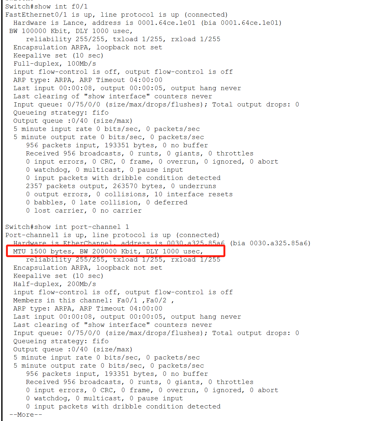
聚合链路配置成功:
物理端口(Fa0/1、Fa0/2)已加入聚合组 Port-channel1。
聚合端口 Port-channel1 的带宽为物理端口之和(200 Mbit/s)。
聚合端口状态为 up/up,表明链路正常工作。
标准ACL配置
在Router2上配置
Router(config)#access-list 1 deny 192.168.2.51 0.0.0.0  // 拒绝192.168.2.51访问Server0
Router(config)#access-list 1 permit any	// 设置默认允许所有	// 将以上配置条目应用到当前接口上
Router(config)#interface Gig0/0
Router(config-if)#ip access-group 1 in	// 将以上配置条目应用到当前接口上
Router(config-if)#ip access-group 1 out	// 控制出口流量
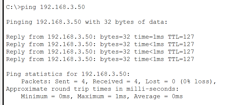
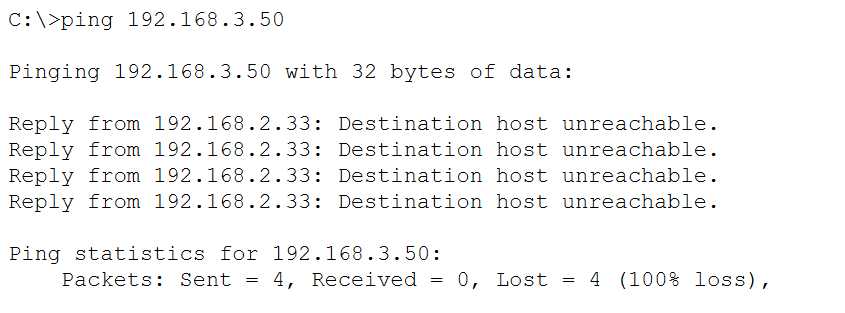
测试连通性:PC4可以访问server0,PC5无法访问server0
PC4 ping server0 测试:
PC5 ping server0 测试
VPN配置:建立GRE隧道
Router7配置:
Router(config)#interface Serial0/3/0
Router(config-if)#ip address 10.1.1.1 255.255.255.0
Router(config-if)#no shutdown
Router(config-if)#exit
Router(config)#ip route 0.0.0.0 0.0.0.0 10.1.1.2
ISP配置:
Router(config)#interface Serial0/2/0
Router(config-if)#ip address 10.1.1.2 255.255.255.0
Router(config-if)#no shutdown
Router(config-if)#exit
Router(config)#interface Serial0/3/0
Router(config-if)#ip address 20.1.1.2 255.255.255.0
Router(config-if)#no shutdown
Router(config-if)#exit
Router9配置:
Router(config)#interface FastEthernet0/0
Router(config-if)#ip address 192.168.2.65 255.255.255.192
Router(config-if)#no shutdown
Router(config-if)#exit
Router(config)#interface Serial0/3/0
Router(config-if)#ip address 20.1.1.1 255.255.255.0
Router(config-if)#no shutdown
Router(config-if)#exit
Router(config)#ip route 0.0.0.0 0.0.0.0 20.1.1.2
建立GRE隧道:
Router7配置:
Router(config)#int tunnel 0
Router(config-if)#ip address 100.1.1.1 255.255.255.0
Router(config-if)#tunnel source s0/3/0
Router(config-if)#tunnel destination 20.1.1.1
Router(config-if)#no shutdown
Router(config-if)#exit
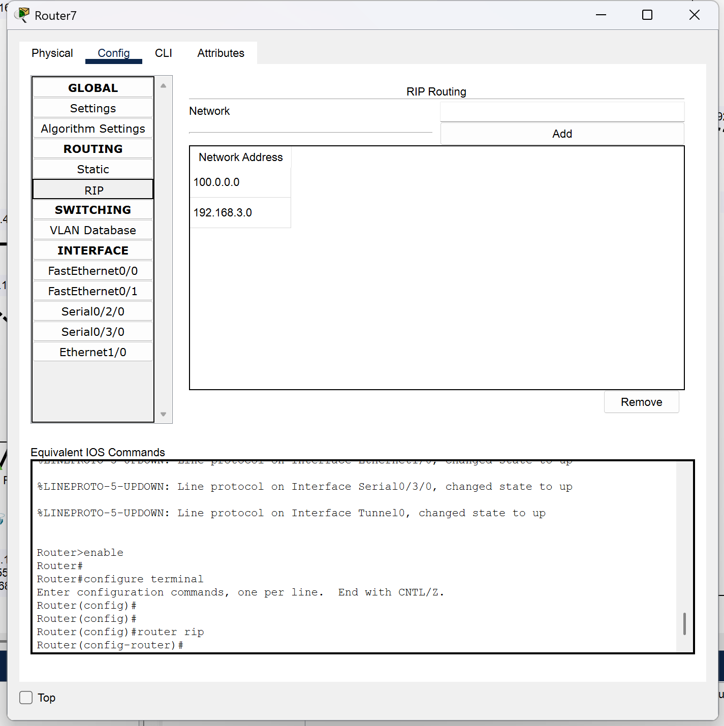
Router(config)#route rip
Router(config-router)#network 100.1.1.0
Router(config-router)#network 192.168.2.33
Router(config-router)#no auto-summary
Router9配置:
Router(config)#int tunnel 0
Router(config-if)#ip address 100.1.1.2 255.255.255.0
Router(config-if)#tunnel source s0/3/0
Router(config-if)#tunnel destination 10.1.1.1
Router(config-if)#no shutdown
Router(config-if)#exit
Router(config)#route rip
Router(config-router)#network 100.1.1.0
Router(config-router)#network 192.168.2.0
Router(config-router)#no auto-summary
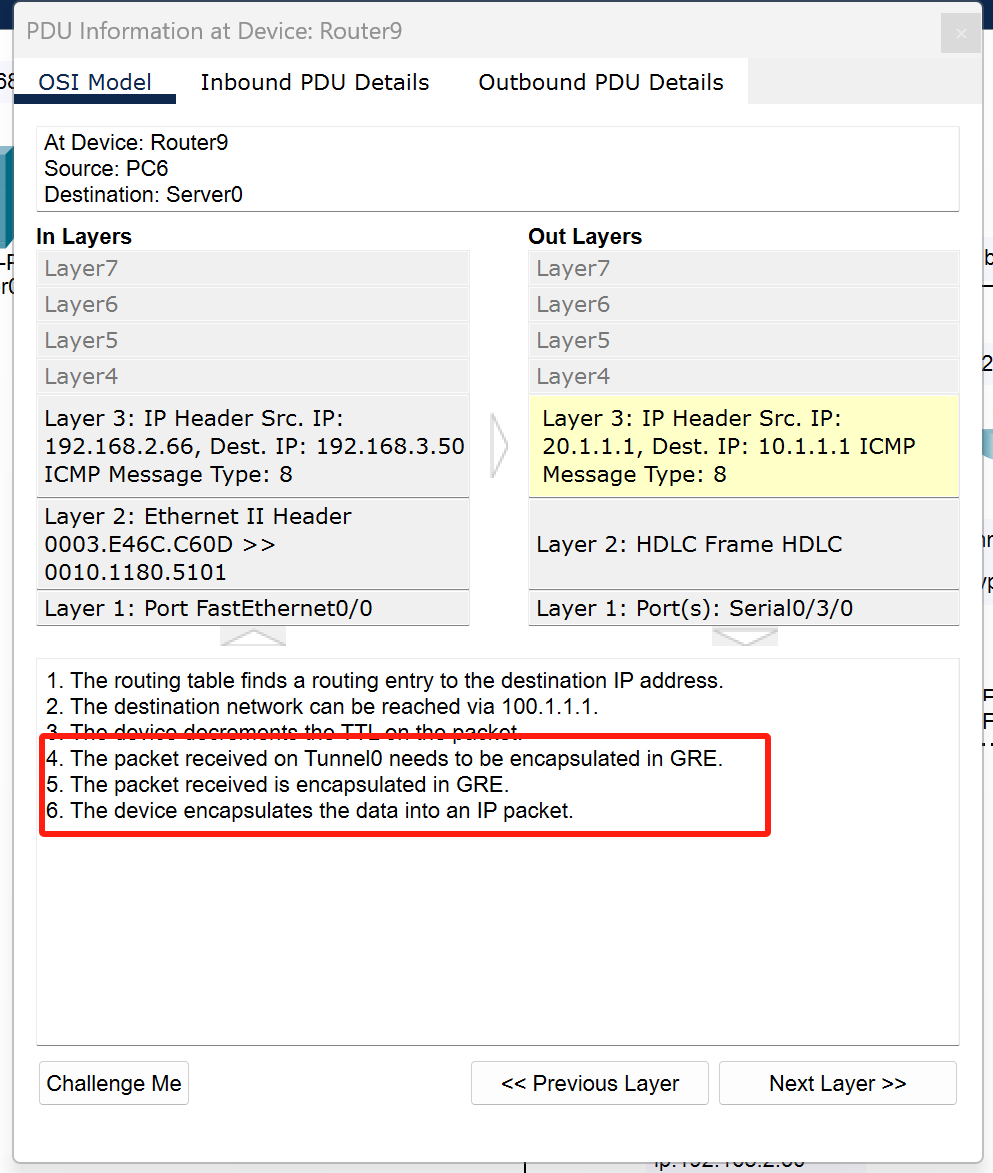
测试VPN技术:
测试主机PC6与外网Server0服务器连通性,通过抓包。目标网络可达,且数据被封装到GRE中,VPN技术实现。
NET技术配置
Router0配置
#将R0的接口f0/0配置为内网接口,接口f0/1配置为外网接口
Router(config-if)#int f0/0
Router(config-if)#ip nat inside
Router(config-if)#exit
Router(config)#int f0/1
Router(config-if)#ip nat outside
Router(config-if)#exit
#将内网主机的私有IP地址映射为公共IP地址
R1(config)#ip nat inside source static 10.0.0.1 192.168.4.3
R1(config)#ip nat inside source static 10.0.0.2 192.168.4.4
R1(config)#exit
查看net配置:show ip nat s
Router#show ip nat s
Total translations: 2 (2 static, 0 dynamic, 0 extended)
Outside Interfaces: FastEthernet0/1
Inside Interfaces: FastEthernet0/0
Hits: 0  Misses: 0
Expired translations: 0
Dynamic mappings:
Router#
Router#show ip nat t
Pro  Inside global     Inside local       Outside local      Outside global
---  192.168.4.3       10.0.0.1           ---                ---
---  192.168.4.4       10.0.0.2           ---                ---
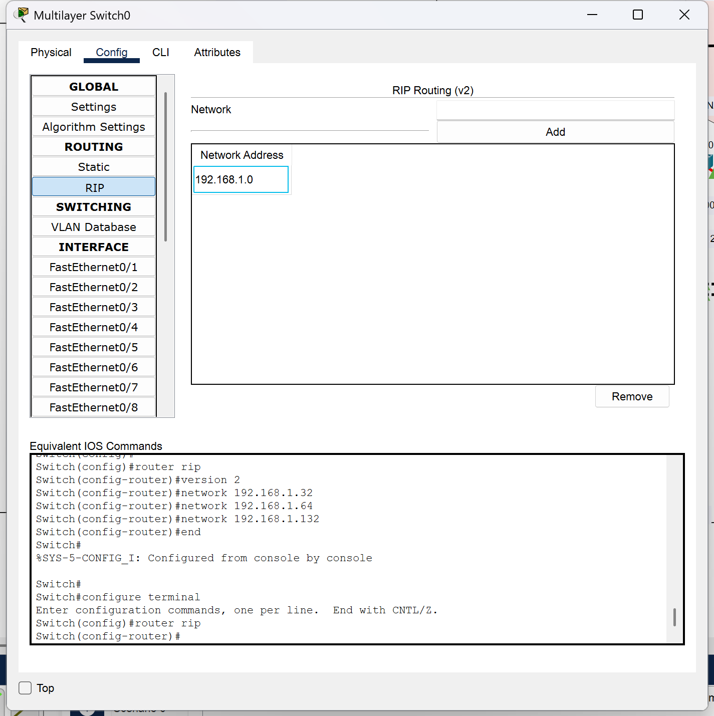
RIP2协议配置
Switch(config)#router rip  //启用RIP路由协议
Switch(config-router)#version 2  //使用RIPv2版本的RIP
Switch(config-router)#network 192.168.1.32 //向RIP中添加ip
Switch(config-router)#network 192.168.1.64
Switch(config-router)#network 192.168.1.132
Switch(config-router)#end
查看配置情况
OSRF协议
Router1配置:
Router(config)#router ospf 100
Router(config-router)#network 192.168.4.0 0.0.0.255 area 1
Router(config-router)#network 192.168.5.0 0.0.0.255 area 1
Router(config-router)#exit
Router2配置:
Router(config)#router ospf 100
Router(config-router)#network 192.168.5.0 0.0.0.255 area 1
Router(config-router)#network 192.168.6.0 0.0.0.255 area 1
Router(config-router)#exit
测试:
show ip ospf neighbor
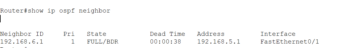
动态、静态路由
Router7:
静态:
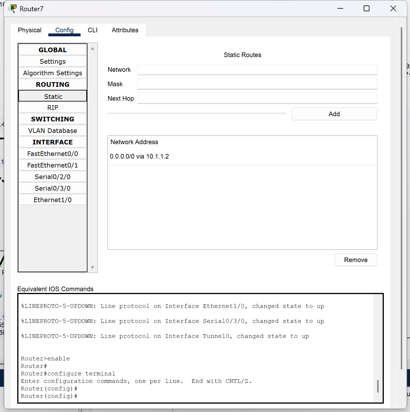
动态: