用串口控制DAC
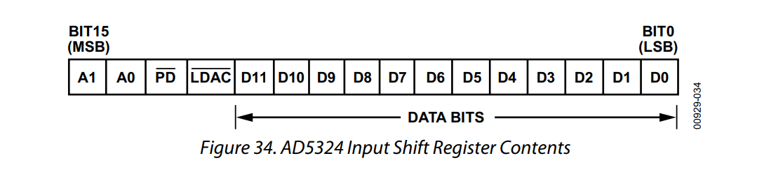
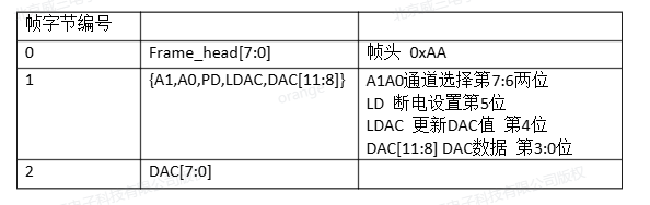
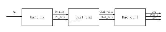
使用串口助手发送四个字节的指令,来控制DAC产生对应数值的电压,第一字节为AA指令,使DAC进入准备状态,以防止串口产生的意外数据进行干扰。第二字节为选择寄存器指令,及(A1和A0),只有最低两位有效。PD和LDAC固定为1和0。第三字节的高4位和第四字节的全部位组成12位的数据位。这样我们可以用状态机来控制串口发来的数据与需要给dac模块的16位数据的关系。
输出的电压(VOUT)与输入的12位数据位的数据(D)公式:
VOUT=VREF * D /2^N。
VREF为参考电压,这里选用2.5V。
N为DAC的分辨率,AD5324的分辨率为12位。
例如:我想在DAC-A通道产生一个1.6V的电压:
那么A1和A0位设置为0、0。PD和LDAC固定为1、0。12位的数据位按照以上公式可以计算:1.6=2.5*D/2^12。计算结果D=2621.44,取近似值2621,用二进制表示为1010_0011_1101。那么串口发送的第一个字节为AA指令,第二字节的最低两位为00,第三字节中的高4位为1010,第四字节为0011_1101。这四个字节用8进制数可以表示为AA 00 A0 3D。
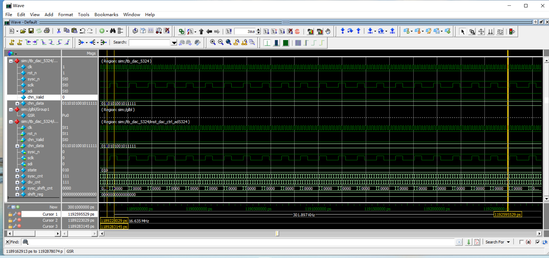
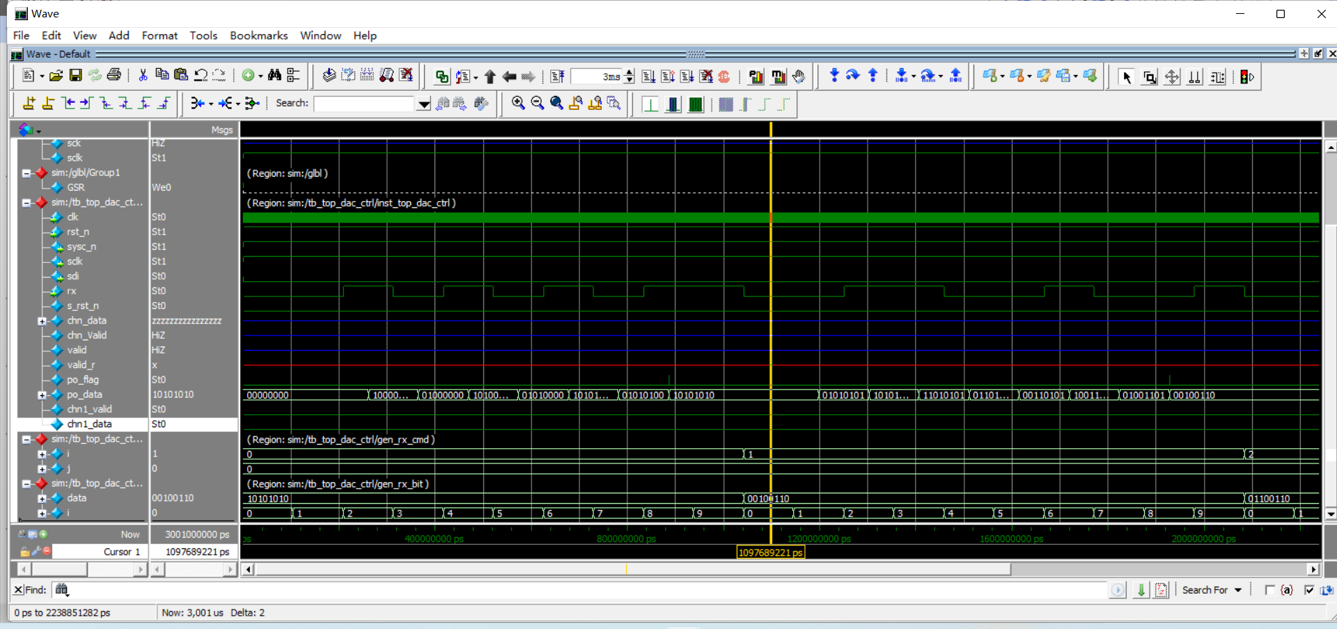
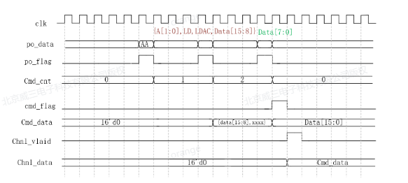
模型模块图和时序图:
// -----------------------------------------------------------------------------
// Copyright (c) 2014-2025 All rights reserved
// -----------------------------------------------------------------------------
// Author : lvjitao lvjitao_o@163.com
// File   : top_dac_ctrl.v
// Create : 2025-10-15 09:48:38
// Revise : 2025-10-16 15:34:58
// Editor : sublime text3, tab size (4)
// -----------------------------------------------------------------------------
`timescale  1ns/1psmodule top_dac_ctrl(input 	wire 	clk,input	wire	rst_n,// input	wire	chn_Valid,// input	wire [15:0]	chn_data,	//(A0, A1, LDAC, DATA[11:0])//SPI DAC masteroutput	wire		sysc_n,output	wire		sclk,output	wire		sdi,//uartinput	wire		rx);wire 			s_rst_n;
wire [15:0]		chn_data;
wire			chn_Valid;wire 	valid;
reg	valid_r;wire	po_flag;
wire[7:0] po_data;reset_gen reset_gen_inst (.clk(clk), .rst_n(rst_n), .s_rst_n(s_rst_n));dac_ctrl_ad5324 dac_ctrl_ad5324_inst(.clk       (clk),.rst_n     (s_rst_n),.chn_Valid (chn_Valid),.chn_data  (chn_data),.sysc_n    (sysc_n),.sclk      (sclk),.sdi       (sdi));ila_top ila_top_inst (.clk(clk), // input wire clk.probe0({sysc_n,sclk,sdi,chn_data,chn_Valid}) // input wire [23:0] probe0);// vio_top vio_top_inst (//   .clk(clk),                // input wire clk//   .probe_out0(valid),  // output wire [0 : 0] probe_out0//   .probe_out1(chn_data)  // output wire [15 : 0] probe_out1// );uart_cmd inst_uart_cmd(.clk        (clk),.rst_n      (rst_n),.pi_flag    (po_flag),.pi_data    (po_data),.chn1_valid (chn1_valid),.chn1_data  (chn1_data));uart_rx #(.CNT_BAUD_MAX(5208),.CNT_HALF_BAUD_MAX(2603)) inst_uart_rx (.clk     (clk),.rst_n   (rst_n),.rx      (rx),.po_data (po_data),.po_flag (po_flag));// always @(posedge clk ) begin
// 	valid_r <= valid;
// end// assign chn_Valid = (valid_r == 1'b0 && valid == 1'b1)? 1'b1 : 1'b0;endmodule
// -----------------------------------------------------------------------------
// Copyright (c) 2014-2025 All rights reserved
// -----------------------------------------------------------------------------
// Author : lvjitao lvjitao_o@163.com
// File : uart_cmd.v
// Create : 2025-10-16 15:30:40
// Revise : 2025-10-16 15:30:40
// Editor : sublime text3, tab size (4)
// -----------------------------------------------------------------------------
`timescale 1ns/1psmodule uart_cmd(input wire clk,input wire rst_n,input wire pi_flag,input wire[7:0] pi_data,output reg chn1_valid,output reg[15:0] chn1_data );reg [1:0] cmd_cnt;
reg [15:0] cmd_data;
reg cmd_flag;always @(posedge clk ) beginif (rst_n == 0) begin// resetcmd_cnt <= 0;endelse if (cmd_cnt == 2 && pi_flag == 1) begincmd_cnt <= 0;endelse if (cmd_cnt != 'd0 && pi_flag == 1'b1) begincmd_cnt <= cmd_cnt + 1;endelse if (pi_flag == 1 && pi_data == 8'hAA && cmd_cnt == 'd0) begincmd_cnt <= 1'd1;end
endalways @(posedge clk) beginif (rst_n == 0) begin// resetcmd_data <= 0;endelse if (cmd_cnt == 'd1 && pi_flag == 1'b1) begincmd_data <= {pi_data, cmd_data[7:0]}; endelse if (cmd_cnt <= 'd2 && pi_flag == 1'b1) begincmd_data <= {cmd_data[15:8], pi_data};end
endalways @(posedge clk) beginif (rst_n == 0) begin// resetcmd_flag <= 0;endelse if (cmd_cnt == 'd2 && pi_flag == 1) begincmd_flag <= 1;endelse begincmd_flag <= 1'b0;end
endalways @(posedge clk ) beginchn1_valid <= cmd_flag;
endalways @(posedge clk ) beginif (rst_n == 0) begin// resetchn1_data <= 0;endelse if (cmd_flag == 1) beginchn1_data <= cmd_data;end
endendmodule// This is a simple example.
// You can make a your own header file and set its path to settings.
// (Preferences > Package Settings > Verilog Gadget > Settings - User)
//
// "header": "Packages/Verilog Gadget/template/verilog_header.v"
//
// -----------------------------------------------------------------------------
// Copyright (c) 2014-2023 All rights reserved
// -----------------------------------------------------------------------------
// Author : yongchan jeon (Kris) poucotm@gmail.com
// File : uart_rx.v
// Create : 2023-03-31 11:40:44
// Revise : 2023-04-20 14:06:11
// Editor : sublime text3, tab size (4)
// -----------------------------------------------------------------------------
module uart_rx (input wire clk, input wire rst_n, input wire rx, output reg [7:0] po_data,output reg po_flag);reg rx1;
reg rx2;
reg rx2_reg;
reg rx_flag;
reg [12:0] cnt_baud;
reg bit_flag;
reg [3:0] bit_cnt;parameter CNT_BAUD_MAX = 5207;
parameter CNT_HALF_BAUD_MAX = 2603;
//rx1
always @(posedge clk or negedge rst_n) begin if(rst_n == 1'b0) beginrx1 <= 1'b1;end else beginrx1 <= rx;end
end//rx2
always @(posedge clk or negedge rst_n) begin if(rst_n == 1'b0) beginrx2 <= 1'b1;end else beginrx2 <= rx1;end
end//rx2_reg
always @(posedge clk or negedge rst_n) begin if(rst_n == 1'b0) beginrx2_reg <= 1'b1;end else beginrx2_reg <= rx2;end
end
//rx_flag
always @(posedge clk or negedge rst_n) begin if(rst_n == 1'b0) beginrx_flag <= 1'b0;end else if (bit_cnt == 'd8&&bit_flag==1'b1) beginrx_flag <= 1'b0;endelse if(rx2==1'b0&&rx2_reg==1'b1)beginrx_flag <= 1'b1;endend//cnt_baud
always @(posedge clk or negedge rst_n) begin if(rst_n == 1'b0) begincnt_baud <= 'd0;end else if(bit_flag == 1'b1 && bit_cnt == 'd8)begincnt_baud <= 'd0;endelse if (cnt_baud == CNT_BAUD_MAX && rx_flag == 1'b1) begincnt_baud <= 'd0;endelse if (rx_flag == 1'b1) begincnt_baud <= cnt_baud + 1'b1;end
end//bit_flag
always @(posedge clk or negedge rst_n) begin if(rst_n == 1'b0) beginbit_flag <= 1'b0;end else if(cnt_baud == CNT_HALF_BAUD_MAX && rx_flag == 1'b1)beginbit_flag <= 1'b1;endelse beginbit_flag <= 1'b0;end
end//bit_cnt
always @(posedge clk or negedge rst_n) begin if(rst_n == 1'b0) beginbit_cnt <= 'd0;end else if(bit_flag == 1'b1 && bit_cnt == 'd8)beginbit_cnt <= 1'b0;endelse if (bit_flag == 1'b1) beginbit_cnt <= bit_cnt + 1'b1;end
end//po_data
always @(posedge clk or negedge rst_n) begin if(rst_n == 1'b0) beginpo_data <= 'd0;end else if(bit_cnt>= 'd1 && bit_flag == 1'b1)beginpo_data <= {rx2_reg,po_data[7:1]};end
end//po_flag
always @(posedge clk or negedge rst_n) begin if(rst_n == 1'b0) beginpo_flag <= 1'b0;end else if(bit_cnt == 'd8 && bit_flag == 1'b1)beginpo_flag <= 1'b1;endelse beginpo_flag <= 1'b0;end
endendmodule