[OpenGL]简单几何类设计
目录
一、整体的设计
二、创建正方体
三、创建球体
四、几何类的代码
前言:刚学OpenGL,主要想要记录下学到的东西,也当作一个笔记,部分理解可能有偏差,也是不全面的,如果有发现问题的话也很高兴大家可以指正,我会尽快修改的,在后续学习过程中,也会进行相应的补充与修改。(课件截图来源于bilibili赵新政老师)
(说明:本文章主要是想要记录球体的实现,几何类只是简单的封装)
(OpenGL老师:赵新政的个人空间-赵新政个人主页-哔哩哔哩视频)

一、整体的设计
在去构建一个图形的时候,总是会需要去创建一大堆的东西,像是vbo,ebo,vao等。在很多时候,都需要去创建许许多多的图形,而为了增加代码的复用性,就完全可以将创建的这一过程封装起来 。(在这里的话将会以创建正方体与球体为例进行设计)
为了创建这样的几何图形,肯定是要去记录他的位置数据以及uv数据的,我们需要通过vbo去保存这些数据,并将他们绑定到对应vao上。同时我们需要使用ebo去记录需要去绘制的点。由于在渲染的时候我们需要绑定当前vao,所以也需要对外暴露获取vao的接口。在使用glDrawElements的时候,需要提供绘制顶点的个数,因而也需要记录绘制顶点的个数并提供对应的接口。
#pragma once#include"core.h"class Geometry
{
public:Geometry();~Geometry();static Geometry* create_box(float size);static Geometry* create_sphere(float radius);GLuint get_vao() const{return m_vao;}uint32_t get_indices_count() const{return m_indices_count;}private:GLuint m_vao{ 0 };GLuint m_pos_vbo{ 0 };GLuint m_uv_vbo{ 0 };GLuint m_ebo{ 0 };uint32_t m_indices_count{ 0 };};
二、创建正方体
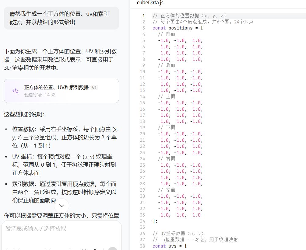
对于一个正方体而言,需要什么具体的顶点数据想必大家都是清楚的,但是一个个去敲这些数据显然是太麻烦了,不过,你觉得麻烦的东西自然有的是AI做。
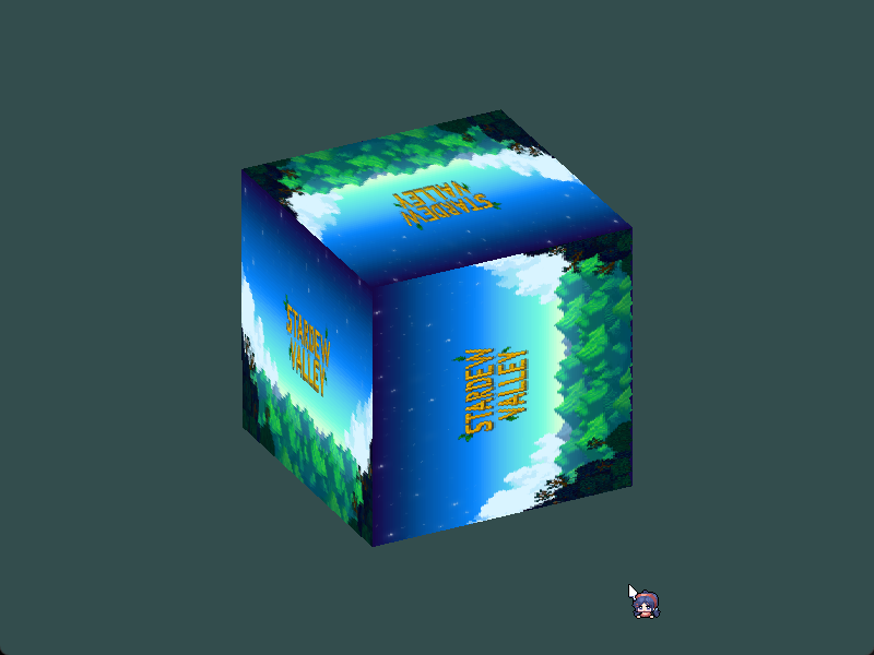
效果展示:
Geometry* Geometry::create_box(float size)
{Geometry* geometry = new Geometry();float half_size = size / 2.0f;float positions[] = {// 前面-half_size, -half_size,  half_size,half_size, -half_size,  half_size,half_size,  half_size,  half_size,-half_size,  half_size,  half_size,// 后面-half_size, -half_size, -half_size,-half_size,  half_size, -half_size,half_size,  half_size, -half_size,half_size, -half_size, -half_size,// 上面-half_size,  half_size, -half_size,-half_size,  half_size,  half_size,half_size,  half_size,  half_size,half_size,  half_size, -half_size,// 下面-half_size, -half_size, -half_size,half_size, -half_size, -half_size,half_size, -half_size,  half_size,-half_size, -half_size,  half_size,// 右面half_size, -half_size, -half_size,half_size,  half_size, -half_size,half_size,  half_size,  half_size,half_size, -half_size,  half_size,// 左面-half_size, -half_size, -half_size,-half_size, -half_size,  half_size,-half_size,  half_size,  half_size,-half_size,  half_size, -half_size};float uvs[] = {// 前面0.0, 0.0,1.0, 0.0,1.0, 1.0,0.0, 1.0,// 后面0.0, 0.0,1.0, 0.0,1.0, 1.0,0.0, 1.0,// 上面0.0, 0.0,1.0, 0.0,1.0, 1.0,0.0, 1.0,// 下面0.0, 0.0,1.0, 0.0,1.0, 1.0,0.0, 1.0,// 右面0.0, 0.0,1.0, 0.0,1.0, 1.0,0.0, 1.0,// 左面0.0, 0.0,1.0, 0.0,1.0, 1.0,0.0, 1.0};unsigned int indices[] = {// 前面0, 1, 2,2,3,0,// 后面4, 5, 6,6,7,4,// 上面8, 9, 10,10, 11,8,// 下面12, 13, 14,14,15,12,// 右面16, 17, 18,18, 19,16,// 左面20, 21, 22,22, 23,20};//2. 创建VBOGLuint &pos_vbo=geometry->m_pos_vbo,&uv_vbo=geometry->m_uv_vbo,&ebo=geometry->m_ebo;glGenBuffers(1, &pos_vbo);glBindBuffer(GL_ARRAY_BUFFER, pos_vbo);glBufferData(GL_ARRAY_BUFFER, sizeof(positions), positions, GL_STATIC_DRAW);glGenBuffers(1, &uv_vbo);glBindBuffer(GL_ARRAY_BUFFER, uv_vbo);glBufferData(GL_ARRAY_BUFFER, sizeof(uvs), uvs, GL_STATIC_DRAW);//3. 创建EBOglGenBuffers(1, &ebo);glBindBuffer(GL_ELEMENT_ARRAY_BUFFER, ebo);glBufferData(GL_ELEMENT_ARRAY_BUFFER, sizeof(indices), indices, GL_STATIC_DRAW);geometry->m_indices_count = sizeof(indices) / sizeof(indices[0]);//4. 创建VAOglGenVertexArrays(1, &geometry->m_vao);glBindVertexArray(geometry->m_vao);glBindBuffer(GL_ARRAY_BUFFER, pos_vbo);glEnableVertexAttribArray(0);glVertexAttribPointer(0, 3, GL_FLOAT, GL_FALSE, sizeof(float) * 3, (void*)0);glBindBuffer(GL_ARRAY_BUFFER, uv_vbo);glEnableVertexAttribArray(1);glVertexAttribPointer(1, 2, GL_FLOAT, GL_FALSE, sizeof(float) * 2, (void*)0);//5. 绑定EBOglBindBuffer(GL_ELEMENT_ARRAY_BUFFER, geometry->m_ebo);glBindVertexArray(0);return geometry;
}
三、创建球体
在进行学习之前,对于创建球体我是没有任何思路的,我认为这本身就是抽象的,相较于创建棱角分明的正方体,球体的曲面令人无从下手,如何去获取顶点数据成了一个难题。
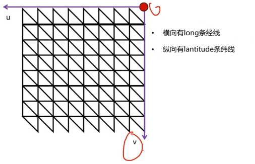
球体可以看作是经纬线分布组成的集合体,每一个经线跟纬线的焦点,都可以视作一个顶点,而确定了经线条数(long)与纬线条数(latitude)就可以锁定球体的精度(肯定是越多显得越浑圆)。(课件截图来源于bilibili赵新政)
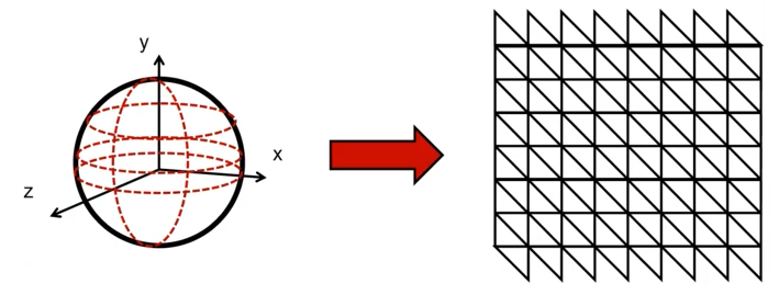
在这个基础上,就已经显现出计算顶点位置的思路了,我们只需要选取一条经线与一条纬线,去计算其交点的位置即可。结合几何知识,从图中的表示可以得出:
y=radius*cos(phi)
x=radius*sin(phi)*cos(theta)
z=radius*sin(phi)*sin(theta)

但是,在上述的表达式中,phi和theta角是未知的,那么接下来的问题便是解决角度的计算问题。
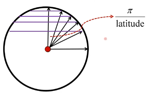
在计算角度的过程当中,这里是将球体看作半条经线(一个半圆)绕着圆周旋转一圈所得到。(★)
取纬线截面进行观察,可以发现每个小角都是被纬线等分得到,可知纬线角=Π/latitude。同理可得经线角=2Π/long。(这个公式与标★那句是紧密相关的)最终的phi/theta也就是经线角/纬线角乘以当前线的索引(第几条)。因而,只需要使用两层循环遍历纬线和经线,就可以得计算得到坐标了。(long为经线段数,latitude为纬线段数)
那么接下来需要处理uv数据。从展开图去分析,uv数据实际上也是被经纬线所等分,那么u=j/long,v=i/latitude。(j,i为当前遍历到的第几条经纬线)由于这里演示的uv坐标轴与实际的uv坐标轴是放过来的,因而需要取补。实际的u=1.0-j/long,v=1.0-i/latitude。
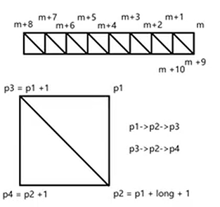
最后,就只需要取计算索引了。取出展开图中的一个矩形,记其右上角坐标为p1,那么右下角坐标就是由p1经过了纬线条数个顶点+1后所得到的顶点(展开图左右/上下的线实际上是同一条,两条线是重合的,因而在计算时需要+1),p2=p1+long+1,相应的左上角顶点就是p1+1,左下角顶点就是p2+1。
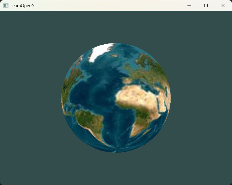
代码与效果演示:
Geometry* Geometry::create_sphere(float radius)
{Geometry* geometry = new Geometry();//1.位置 2.uv 3.索引//1.主要变量声明std::vector<GLfloat>positions{};std::vector<GLfloat>uvs{};std::vector<GLuint>indices{};//声明经线与纬线的数量int numLatLines = 60;int numLongLines = 60;//2.通过两层循环(纬线在外,经线在内)===>位置、uvfor (int i = 0; i <= numLatLines; i++){for (int j = 0; j <= numLongLines; j++){float phi = glm::pi<float>() * i / numLatLines;float theta = 2 * glm::pi<float>() * j / numLongLines;float y = radius * cos(phi);float x = radius * sin(phi) * cos(theta);float z = radius * sin(phi) * sin(theta);positions.push_back(x);positions.push_back(y);positions.push_back(z);float u = 1.0 - (float)j / (float)numLongLines;float v = 1.0 - (float)i / (float)numLatLines;uvs.push_back(u);uvs.push_back(v);}}//3.通过两层循环得到顶点索引for (int i = 0; i < numLatLines; i++){for (int j = 0; j < numLongLines; j++){int p1 = i * (numLongLines + 1) + j;int p2 = p1 + numLongLines + 1;int p3 = p1 + 1;int p4 = p2 + 1;indices.push_back(p1);indices.push_back(p2);indices.push_back(p3);indices.push_back(p3);indices.push_back(p2);indices.push_back(p4);}}//4.生成vbo与vaoGLuint& pos_vbo = geometry->m_pos_vbo, & uv_vbo = geometry->m_uv_vbo, & ebo = geometry->m_ebo;glGenBuffers(1, &pos_vbo);glBindBuffer(GL_ARRAY_BUFFER, pos_vbo);glBufferData(GL_ARRAY_BUFFER, positions.size() * sizeof(float), positions.data(), GL_STATIC_DRAW);glGenBuffers(1, &uv_vbo);glBindBuffer(GL_ARRAY_BUFFER, uv_vbo);glBufferData(GL_ARRAY_BUFFER, uvs.size() * sizeof(float), uvs.data(), GL_STATIC_DRAW);glGenBuffers(1, &ebo);glBindBuffer(GL_ELEMENT_ARRAY_BUFFER, ebo);glBufferData(GL_ELEMENT_ARRAY_BUFFER, indices.size() * sizeof(GLuint), indices.data(), GL_STATIC_DRAW);glGenVertexArrays(1, &geometry->m_vao);glBindVertexArray(geometry->m_vao);glBindBuffer(GL_ARRAY_BUFFER, pos_vbo);glEnableVertexAttribArray(0);glVertexAttribPointer(0, 3, GL_FLOAT, GL_FALSE, sizeof(float) * 3, (void*)0);glBindBuffer(GL_ARRAY_BUFFER, uv_vbo);glEnableVertexAttribArray(1);glVertexAttribPointer(1, 2, GL_FLOAT, GL_FALSE, sizeof(float) * 2, (void*)0);glBindBuffer(GL_ELEMENT_ARRAY_BUFFER, geometry->m_ebo);glBindVertexArray(0);geometry->m_indices_count = indices.size();return geometry;
}
四、几何类的代码
我想你一定不会忘记在析构的时候把相关数据释放掉的~
geometry.h
#pragma once#include"core.h"class Geometry
{
public:Geometry();~Geometry();static Geometry* create_box(float size);static Geometry* create_sphere(float radius);GLuint get_vao() const{return m_vao;}uint32_t get_indices_count() const{return m_indices_count;}private:GLuint m_vao{ 0 };GLuint m_pos_vbo{ 0 };GLuint m_uv_vbo{ 0 };GLuint m_ebo{ 0 };uint32_t m_indices_count{ 0 };};
geometry.cpp
#include"geometry.h"
#include<vector>Geometry::Geometry()
{}
Geometry::~Geometry()
{if(m_vao!=0)glDeleteVertexArrays(1, &m_vao);if(m_pos_vbo!=0)glDeleteBuffers(1, &m_pos_vbo);if(m_uv_vbo!=0)glDeleteBuffers(1, &m_uv_vbo);if(m_ebo!=0)glDeleteBuffers(1, &m_ebo);
}Geometry* Geometry::create_box(float size)
{Geometry* geometry = new Geometry();float half_size = size / 2.0f;float positions[] = {// 前面-half_size, -half_size,  half_size,half_size, -half_size,  half_size,half_size,  half_size,  half_size,-half_size,  half_size,  half_size,// 后面-half_size, -half_size, -half_size,-half_size,  half_size, -half_size,half_size,  half_size, -half_size,half_size, -half_size, -half_size,// 上面-half_size,  half_size, -half_size,-half_size,  half_size,  half_size,half_size,  half_size,  half_size,half_size,  half_size, -half_size,// 下面-half_size, -half_size, -half_size,half_size, -half_size, -half_size,half_size, -half_size,  half_size,-half_size, -half_size,  half_size,// 右面half_size, -half_size, -half_size,half_size,  half_size, -half_size,half_size,  half_size,  half_size,half_size, -half_size,  half_size,// 左面-half_size, -half_size, -half_size,-half_size, -half_size,  half_size,-half_size,  half_size,  half_size,-half_size,  half_size, -half_size};float uvs[] = {// 前面0.0, 0.0,1.0, 0.0,1.0, 1.0,0.0, 1.0,// 后面0.0, 0.0,1.0, 0.0,1.0, 1.0,0.0, 1.0,// 上面0.0, 0.0,1.0, 0.0,1.0, 1.0,0.0, 1.0,// 下面0.0, 0.0,1.0, 0.0,1.0, 1.0,0.0, 1.0,// 右面0.0, 0.0,1.0, 0.0,1.0, 1.0,0.0, 1.0,// 左面0.0, 0.0,1.0, 0.0,1.0, 1.0,0.0, 1.0};unsigned int indices[] = {// 前面0, 1, 2,2,3,0,// 后面4, 5, 6,6,7,4,// 上面8, 9, 10,10, 11,8,// 下面12, 13, 14,14,15,12,// 右面16, 17, 18,18, 19,16,// 左面20, 21, 22,22, 23,20};//2. 创建VBOGLuint &pos_vbo=geometry->m_pos_vbo,&uv_vbo=geometry->m_uv_vbo,&ebo=geometry->m_ebo;glGenBuffers(1, &pos_vbo);glBindBuffer(GL_ARRAY_BUFFER, pos_vbo);glBufferData(GL_ARRAY_BUFFER, sizeof(positions), positions, GL_STATIC_DRAW);glGenBuffers(1, &uv_vbo);glBindBuffer(GL_ARRAY_BUFFER, uv_vbo);glBufferData(GL_ARRAY_BUFFER, sizeof(uvs), uvs, GL_STATIC_DRAW);//3. 创建EBOglGenBuffers(1, &ebo);glBindBuffer(GL_ELEMENT_ARRAY_BUFFER, ebo);glBufferData(GL_ELEMENT_ARRAY_BUFFER, sizeof(indices), indices, GL_STATIC_DRAW);geometry->m_indices_count = sizeof(indices) / sizeof(indices[0]);//4. 创建VAOglGenVertexArrays(1, &geometry->m_vao);glBindVertexArray(geometry->m_vao);glBindBuffer(GL_ARRAY_BUFFER, pos_vbo);glEnableVertexAttribArray(0);glVertexAttribPointer(0, 3, GL_FLOAT, GL_FALSE, sizeof(float) * 3, (void*)0);glBindBuffer(GL_ARRAY_BUFFER, uv_vbo);glEnableVertexAttribArray(1);glVertexAttribPointer(1, 2, GL_FLOAT, GL_FALSE, sizeof(float) * 2, (void*)0);//5. 绑定EBOglBindBuffer(GL_ELEMENT_ARRAY_BUFFER, geometry->m_ebo);glBindVertexArray(0);return geometry;
}
Geometry* Geometry::create_sphere(float radius)
{Geometry* geometry = new Geometry();//1.位置 2.uv 3.索引//1.主要变量声明std::vector<GLfloat>positions{};std::vector<GLfloat>uvs{};std::vector<GLuint>indices{};//声明经线与纬线的数量int numLatLines = 60;int numLongLines = 60;//2.通过两层循环(纬线在外,经线在内)===>位置、uvfor (int i = 0; i <= numLatLines; i++){for (int j = 0; j <= numLongLines; j++){float phi = glm::pi<float>() * i / numLatLines;float theta = 2 * glm::pi<float>() * j / numLongLines;float y = radius * cos(phi);float x = radius * sin(phi) * cos(theta);float z = radius * sin(phi) * sin(theta);positions.push_back(x);positions.push_back(y);positions.push_back(z);float u = 1.0 - (float)j / (float)numLongLines;float v = 1.0 - (float)i / (float)numLatLines;uvs.push_back(u);uvs.push_back(v);}}//3.通过两层循环得到顶点索引for (int i = 0; i < numLatLines; i++){for (int j = 0; j < numLongLines; j++){int p1 = i * (numLongLines + 1) + j;int p2 = p1 + numLongLines + 1;int p3 = p1 + 1;int p4 = p2 + 1;indices.push_back(p1);indices.push_back(p2);indices.push_back(p3);indices.push_back(p3);indices.push_back(p2);indices.push_back(p4);}}//4.生成vbo与vaoGLuint& pos_vbo = geometry->m_pos_vbo, & uv_vbo = geometry->m_uv_vbo, & ebo = geometry->m_ebo;glGenBuffers(1, &pos_vbo);glBindBuffer(GL_ARRAY_BUFFER, pos_vbo);glBufferData(GL_ARRAY_BUFFER, positions.size() * sizeof(float), positions.data(), GL_STATIC_DRAW);glGenBuffers(1, &uv_vbo);glBindBuffer(GL_ARRAY_BUFFER, uv_vbo);glBufferData(GL_ARRAY_BUFFER, uvs.size() * sizeof(float), uvs.data(), GL_STATIC_DRAW);glGenBuffers(1, &ebo);glBindBuffer(GL_ELEMENT_ARRAY_BUFFER, ebo);glBufferData(GL_ELEMENT_ARRAY_BUFFER, indices.size() * sizeof(GLuint), indices.data(), GL_STATIC_DRAW);glGenVertexArrays(1, &geometry->m_vao);glBindVertexArray(geometry->m_vao);glBindBuffer(GL_ARRAY_BUFFER, pos_vbo);glEnableVertexAttribArray(0);glVertexAttribPointer(0, 3, GL_FLOAT, GL_FALSE, sizeof(float) * 3, (void*)0);glBindBuffer(GL_ARRAY_BUFFER, uv_vbo);glEnableVertexAttribArray(1);glVertexAttribPointer(1, 2, GL_FLOAT, GL_FALSE, sizeof(float) * 2, (void*)0);glBindBuffer(GL_ELEMENT_ARRAY_BUFFER, geometry->m_ebo);glBindVertexArray(0);geometry->m_indices_count = indices.size();return geometry;
}