基于EB的K3XX_GPT定时器中断的实现方法
在这里使用了借用了EB官方的demo,实现的效果每1S产生一个中断,实现LED的亮灭。
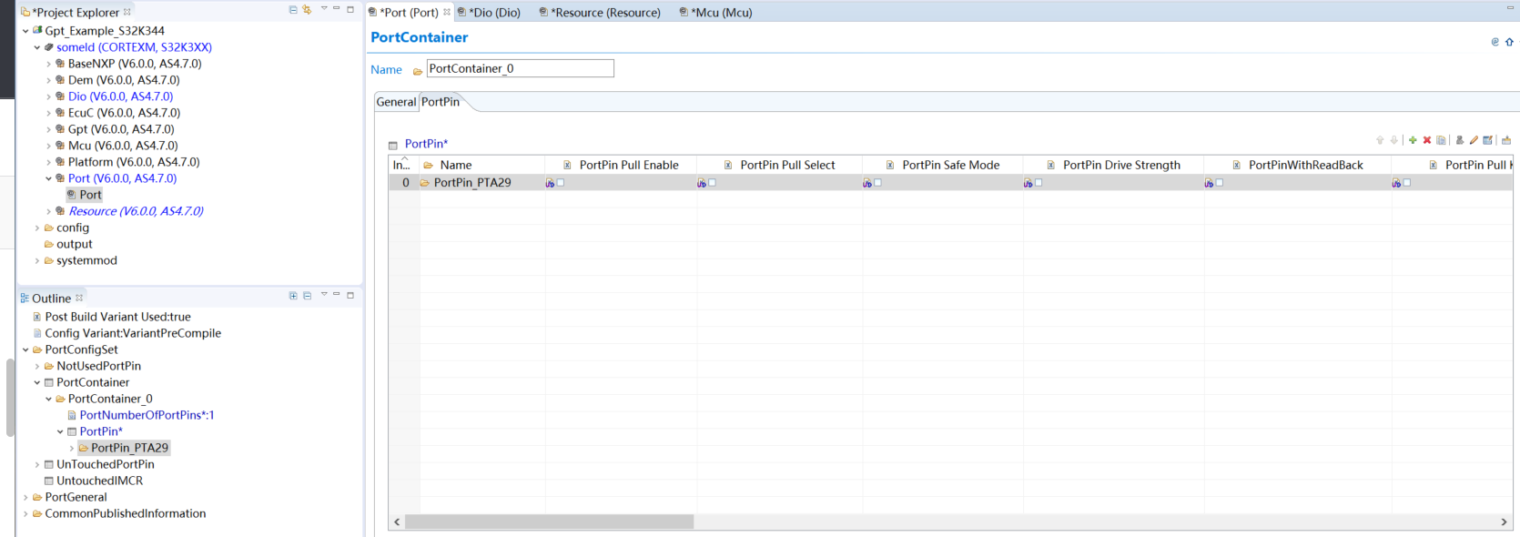
首先在port配置中仅到PTA29,这是一个LED灯控制信号。
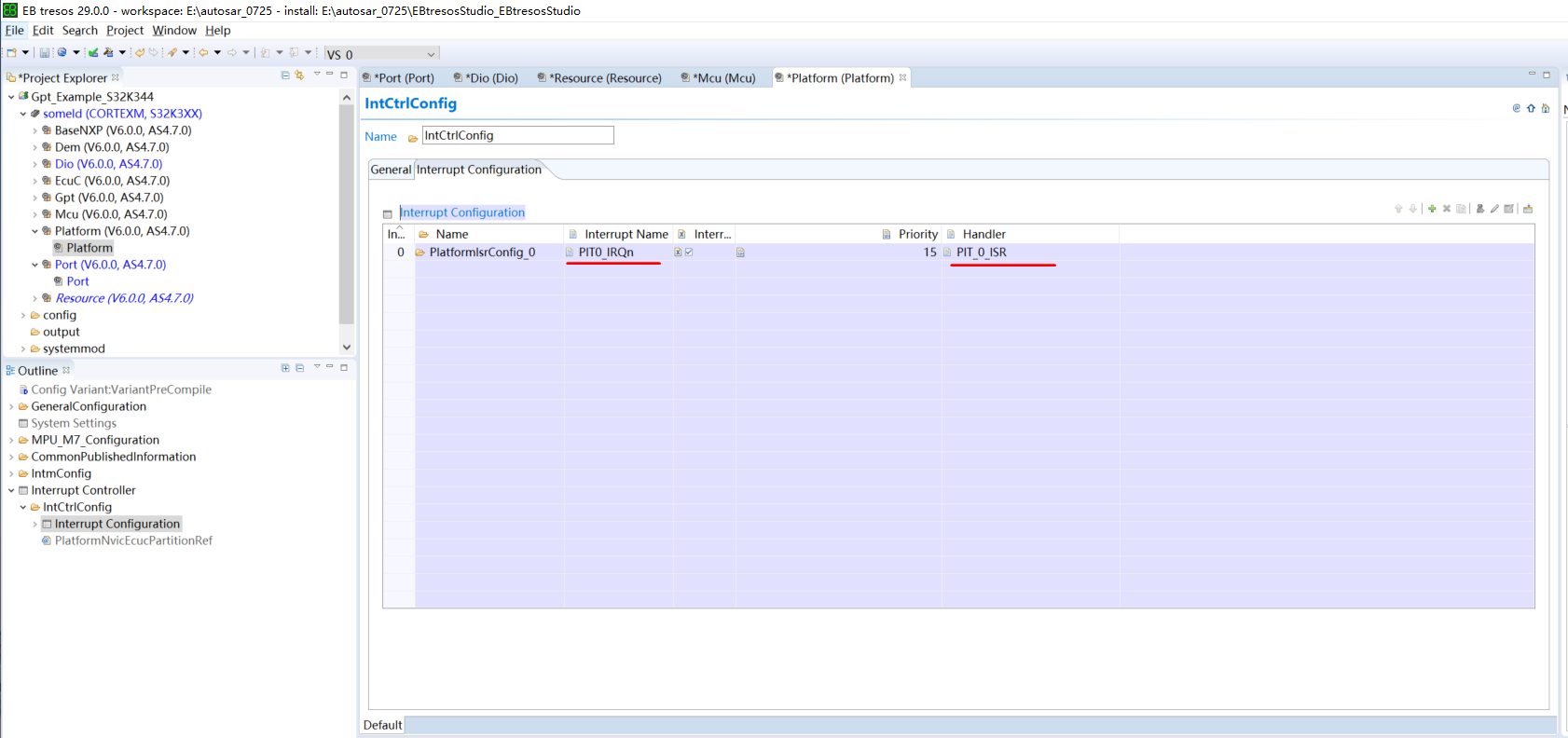
在platform中加入PIT中断,因为GPT计数器可以利用PIT中断。
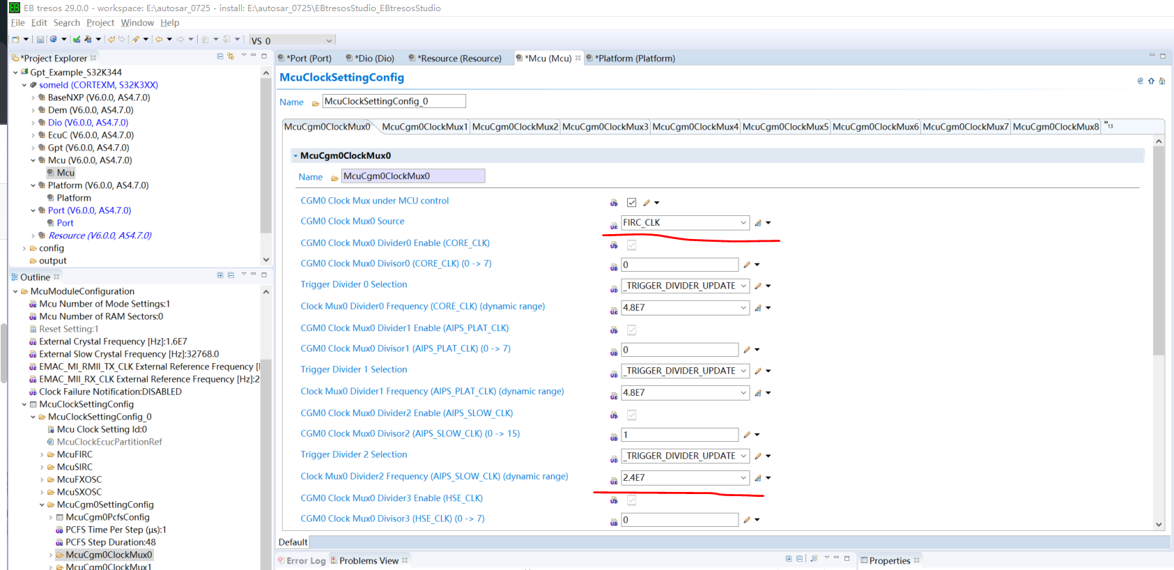
在MCU的时钟配置中,保持demo的默认配置,使用AIPS_SLOW_CLK时钟,其时钟源为FIRC内部时钟,时钟频率为24M
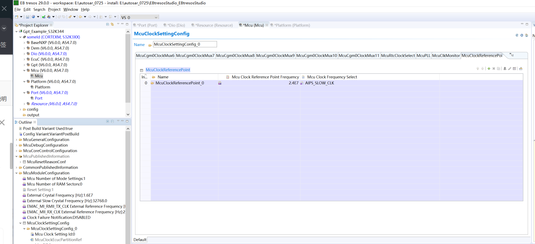
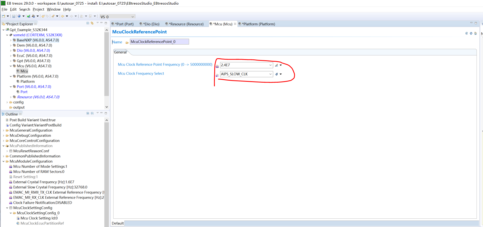
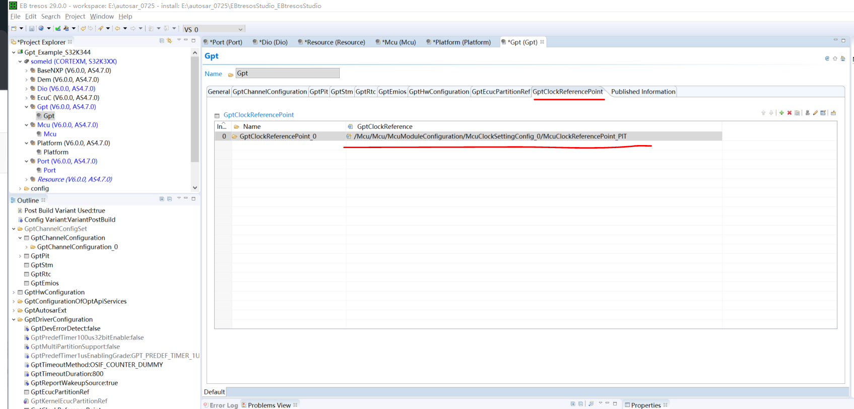
然后在GPT配置中导入该参考时钟源,注意使用的是PIT类型的计数器,要选择CONTINUOUS,这样才会一直产生中断,如果是ONE_SHOT则只有一次中断产生。
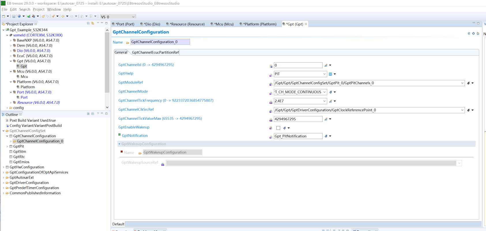
最后生成代码,代码例程也是官方demo中的
void Gpt_PitNotification(void)
{cntt++;toggleLed = 1U;
}/**
* @brief        Main function of the example
* @details      Initializes the used drivers and uses the Gpt
*               and Dio drivers to toggle a LED periodically
*/
int main(void)
{uint8 count = 0U;uint8 pinValue = STD_LOW;/* Init clock */
#if (STD_ON == MCU_PRECOMPILE_SUPPORT)Mcu_Init(NULL_PTR);
#elseMcu_Init(&Mcu_Config_VS_0);
#endif#if (STD_ON == MCU_INIT_CLOCK)/* Initialize the clock tree and apply PLL as system clock */Mcu_InitClock(McuClockSettingConfig_0);#else#error "The Mcu Init Clock API should be enabled from the Mcu driver"
#endif/* Initialize all pins using the Port driver */
#if (STD_ON == PORT_PRECOMPILE_SUPPORT)Port_Init(NULL_PTR);
#elsePort_Init(&Port_Config_VS_0);
#endif/* Initialize Platform driver */Platform_Init(NULL_PTR);/* Initialize the high level configuration structure of Gpt driver */
#if (STD_ON == GPT_PRECOMPILE_SUPPORT)Gpt_Init(NULL_PTR);
#elseGpt_Init(&Gpt_Config_VS_0);
#endif/* Start the Gpt timer */Gpt_StartTimer(GptConf_GptChannelConfiguration_GptChannelConfiguration_0, 24000000U);/* Enable the Gpt notification to get the event for toggling the LED periodically */Gpt_EnableNotification(GptConf_GptChannelConfiguration_GptChannelConfiguration_0);while (1){/* Toggle the gpio pin to blink the LED when the Pit notification is called */if (1U == toggleLed){count++;pinValue = (STD_LOW == pinValue) ? STD_HIGH : STD_LOW;Dio_WriteChannel(DioConf_DioChannel_Digital_Output_LED, pinValue);toggleLed = 0U;}}Gpt_StopTimer(GptConf_GptChannelConfiguration_GptChannelConfiguration_0);//    Exit_Example(TRUE);return (0U);
}
由于PIT的时钟为24M,所以Gpt_StartTimer(GptConf_GptChanelConfiguration_GptChannelConfiguration_0, 24000000U);满偏值写入24000000,则可以实现1S的中断。在PIT中断函数中进行CNT自加,与秒表计数对比,可以验证计时频率符合要求。
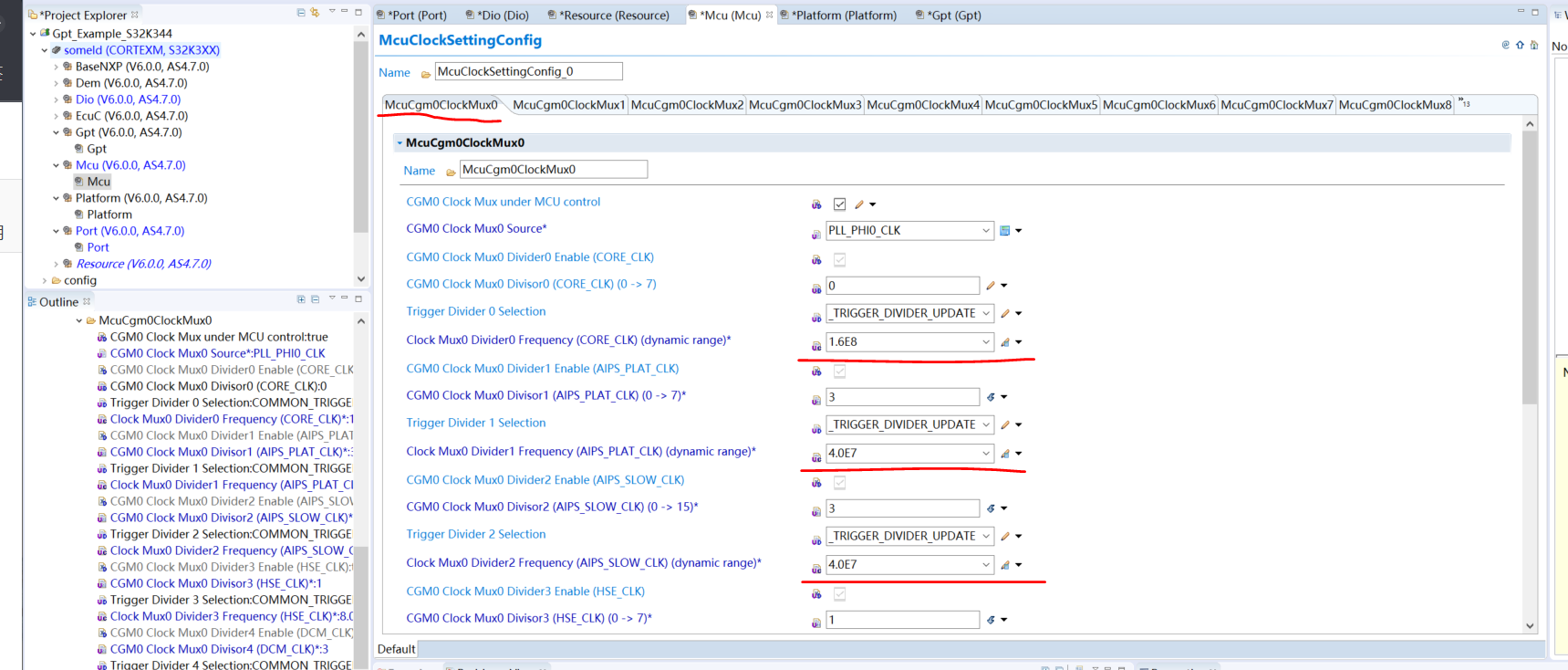
但是,实际上到产品上的板子不会去使用内部时钟,而是外部的晶振的时钟,会更加稳定,所以在MCU的时钟配置中,需要把PIT的源时钟修改为PLL时钟。此处使能PLL锁相环,使能PHI0的分频功能
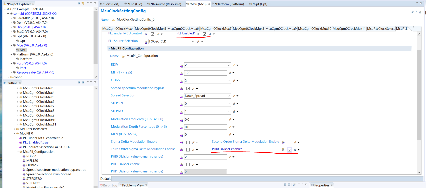
同时VCO和PHI0输出的频率需要更新,点击计算器按钮可以自动更新。
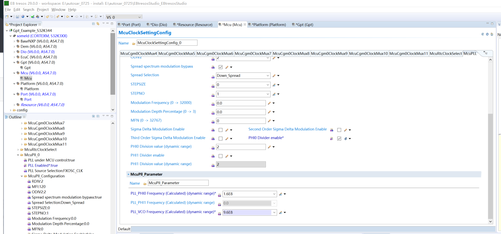
同时MUX0中更新其他分支下的时钟频率
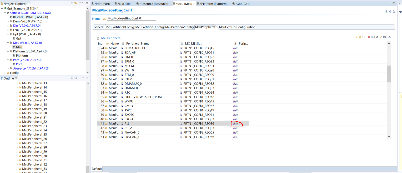
同时在MCUPeripheral中使能PLL时钟
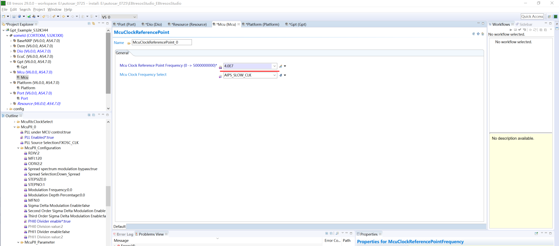
MCU中修改参考源时钟的频率
GPT中加入时间参考源
最后生成相关代码运行即可实现
