自由学习记录(74)
能否把
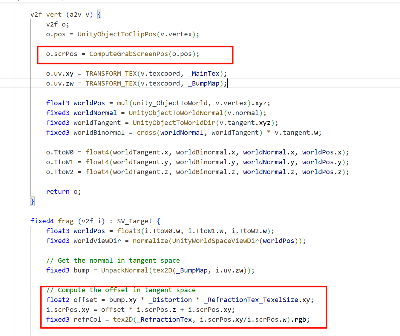
ComputeGrabScreenPos(o.pos)改为ComputeScreenPos(o.pos)?
简而言之——不可以。这两个函数虽然类似,但用途不同,不能互换。
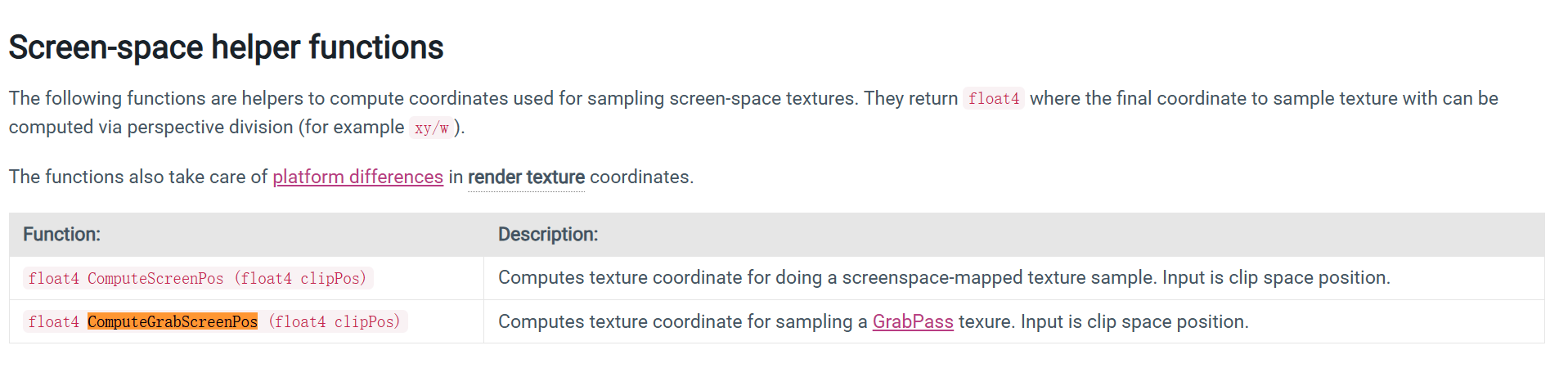
⚙️ 两者区别简明戳表
| 函数 | 用途 | 输出是否适合 GrabPass UV | 是否处理 API 平台差异 |
|---|---|---|---|
ComputeScreenPos(clipPos) | 用于一般屏幕采样(例如在屏幕空间贴图),生成 UV 坐标。 | ❌ 不可靠 | ✅ 处理 NDC 但不考虑 Flip |
ComputeGrabScreenPos(clipPos) | 专门用于 GrabPass 纹理采样,确保 UV 合适 GrabPass 输出格式。 | ✅ 适合 GrabPass | ✅ 包含垂直翻转与 API 差异处理 |
xxxx
总之,想要grabpass使用折射

要先转换成screen pos
采样的时候要/screenpos的w
屏幕空间像素坐标(Screen Space Pixels)
-
这是最直观的概念:例如
Input.mousePosition、Camera.ScreenToWorldPoint()使用的坐标。 -
x∈ [0, ⎯宽度⎯],y∈ [0, ⎯高度⎯],左下或左上角为 (0,0)(视平台而定)Unity Discussions+7Unity Documentation+7Reddit+7Ronja Tutorials+3YouTube+3Unity Discussions+3。 -
这种坐标就是 屏幕上实际像素位置,可直接对应 UI、鼠标位置等。
2. Shader 中 ComputeScreenPos 或 ComputeGrabScreenPos 输出的屏幕坐标
这是属于 图形管线内部的屏幕空间,它的 x, y, z, w 表示方法如下:
• ComputeScreenPos(clipPos)
-
输入是 裁剪空间的
clipPos; -
输出
.xy是齐次空间的屏幕坐标,需透视除以.w→[0,1]的 标准化 UV 坐标(对应整个屏幕区域)Unity Documentation+1Unity Documentation+1; -
.xy/w后的范围才是归一化 UV,不再是像素值。
• ComputeGrabScreenPos(clipPos)
-
功能类似,但专用于 GrabPass 后采样;
-
处理了不同平台纹理 Y 轴的翻转和差异,确保 GrabPass 纹理正确采样️Unity Discussions+9Unity Documentation+9Unity Documentation+9;
-
输出也需要在 fragment shader 做
/w得出 UV。
屏幕坐标系,z依然代表深度值(继承于ndc),只是xy被拉长到1920x1080
z —— 深度值
-
继承自 NDC(Normalized Device Coordinates),表示顶点或片元的深度信息。
-
这个值通常经过非线性压缩:在 D3D 中范围是
[0,1],而 OpenGL 是[-1, +1],经过统一处理后在 URP 中被转换成[0,1]的深度缓冲格式。stackoverflow.comdocs.unity3d.com+6docs.unity3d.com+6docs.unity3d.com+6 -
z可用于世界坐标重构、深度测试、屏幕空间效果等,不是屏幕平面的z = 1。
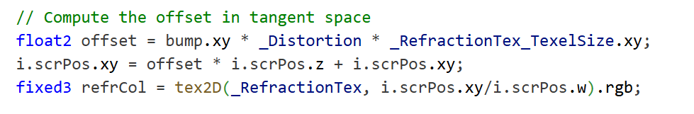
fixed3 refrCol = tex2D(_RefractionTex, i.scrPos.xy / i.scrPos.w).rgb;
这里如果按照一般的屏幕空间,i.scrPos.xy / i.scrPos.w是1920x1080的大坐标,不会在0到1之间采样,
所以说o.scrPos = ComputeGrabScreenPos(o.pos);里的屏幕空间只能算是修改压缩到0到1范围里的方便采样的“屏幕空间”
靠,服了,遭罪的公式,名字起的这么常见的,里面做了什么又不教你,就是硬套是吧,
grabpass硬套,rendertexture还好多了,至少可以当一张正常的图来用
private Texture2D _GenerateProceduralTexture() {Texture2D proceduralTexture = new Texture2D(textureWidth, textureWidth);// The interval between circlesfloat circleInterval = textureWidth / 4.0f;// The radius of circlesfloat radius = textureWidth / 10.0f;// The blur factorfloat edgeBlur = 1.0f / blurFactor;for (int w = 0; w < textureWidth; w++) {for (int h = 0; h < textureWidth; h++) {// Initalize the pixel with background colorColor pixel = backgroundColor;// Draw nine circles one by onefor (int i = 0; i < 3; i++) {for (int j = 0; j < 3; j++) {// Compute the center of current circleVector2 circleCenter = new Vector2(circleInterval * (i + 1), circleInterval * (j + 1));// Compute the distance between the pixel and the centerfloat dist = Vector2.Distance(new Vector2(w, h), circleCenter) - radius;// Blur the edge of the circleColor color = _MixColor(circleColor, new Color(pixel.r, pixel.g, pixel.b, 0.0f), Mathf.SmoothStep(0f, 1.0f, dist * edgeBlur));// Mix the current color with the previous colorpixel = _MixColor(pixel, color, color.a);}}proceduralTexture.SetPixel(w, h, pixel);}}proceduralTexture.Apply();return proceduralTexture;}关键步骤说明:
1. 初始化纹理
Texture2D proceduralTexture = new Texture2D(textureWidth, textureWidth);
生成一个新的空纹理。
2. 准备参数
float circleInterval = textureWidth / 4.0f;
float radius = textureWidth / 10.0f;
float edgeBlur = 1.0f / blurFactor;
-
圆的中心分布在
(1/4, 1/2, 3/4)区域(因为是(i+1)/4) -
每个圆的半径是纹理宽度的 1/10。
-
edgeBlur控制模糊的程度。
3. 遍历每一个像素 (w, h)
for (int w = 0; w < textureWidth; w++) {for (int h = 0; h < textureWidth; h++) {Color pixel = backgroundColor;
为每个像素准备默认色。
4. 遍历 3×3 的圆形位置(九宫格)
for (int i = 0; i < 3; i++) {for (int j = 0; j < 3; j++) {Vector2 circleCenter = new Vector2(circleInterval * (i + 1), circleInterval * (j + 1));float dist = Vector2.Distance(new Vector2(w, h), circleCenter) - radius;
计算每个圆心到当前像素的距离 dist,减去 radius 以判断像素是“在圆内”还是“在边缘”。
5. 进行边缘模糊与颜色混合
Color color = _MixColor(circleColor, new Color(pixel.r, pixel.g, pixel.b, 0.0f), Mathf.SmoothStep(0f, 1.0f, dist * edgeBlur));
pixel = _MixColor(pixel, color, color.a);
-
Mathf.SmoothStep产生平滑插值控制系数(类似高斯边缘) -
_MixColor是作者自定义的线性插值函数,通常是:Color _MixColor(Color a, Color b, float t) {return a * (1 - t) + b * t; } -
第二个参数的 alpha 是 0,表示只淡入圆的颜色边缘,不生硬覆盖背景。
6. 写入纹理像素
proceduralTexture.SetPixel(w, h, pixel);
✅ 最后一步
proceduralTexture.Apply();
这一行是必须的,它会真正把像素数据上传到 GPU。
霜狼_may视频专辑-霜狼_may视频合集-哔哩哔哩视频
xxx
使用程序材质,之所以叫做程序材质,是因为里面用到的纹理是程序生成的纹理(substance designer就是)
程序材质和程序纹理都是sd里生成的
sqad的顶点结构,在模型空间下是竖直排列的
挂在摄像机上面,控制后处理
OnRenderImage(RenderTexture src, RenderTexture dest) 并不是 URP 或 SRP 专属的函数,它实际上是 Unity **内置渲染管线(Built-in Render Pipeline)**中的一项特有功能。
在 URP / HDRP 中是不能用 OnRenderImage 的!
原因:
SRP(Scriptable Render Pipeline)系统重写了整个渲染流程,不再调用 OnRenderImage。
Unity 官方在切换到 URP/HDRP 时明确废弃这类“管线钩子”方式,而转向更加结构化的 Render Feature / Pass injection 机制。
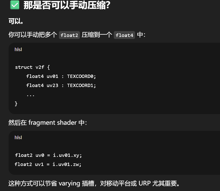
struct v2f {
float4 pos : SV_POSITION;
half2 uv[9] : TEXCOORD0;
};
确实是合法的 HLSL 写法,表示你想把 uv[0] ~ uv[8] 作为 9 个 half2 数据输出到片元着色器。但它是否能“正常运行”取决于 Shader Model(SM)版本 以及你绑定它的目标渲染管线(Built-in / URP / HDRP)和平台(PC / 移动)。
Sobel 卷积计算中,需要 3×3 的纹理采样坐标偏移(UV offset)。
我们是否可以将这些偏移 UV 全部提前在 vertex shader 中计算好,并插值传入 fragment shader,而不在 fragment 中实时计算?
✅ 通常答案是:“可以,而且不会影响结果”
这是因为:
🧠 原因:纹理 UV 插值是线性的,纹理采样坐标偏移也在 UV 空间中是线性的
-
顶点 shader 里计算的每个偏移 UV 是:
uv + offset[i] * texelSize -
然后它们通过 varying 插值进入 fragment shader,UV 插值是线性的
-
最终采样:
tex2D(_MainTex, uv_offset[i])
由于卷积核采样点的坐标本来就是规则排列的(固定步长),所以在 fragment shader 插值得到的 uv_offset[i] 正好是你该采样的位置。
因此:
即使你没在每个 fragment 精确计算采样点偏移,而是通过插值从四个顶点计算过来的值,在大多数情况下它和 fragment 中现算的结果一致。
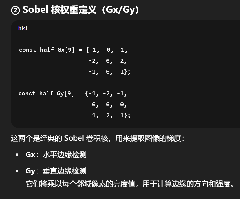
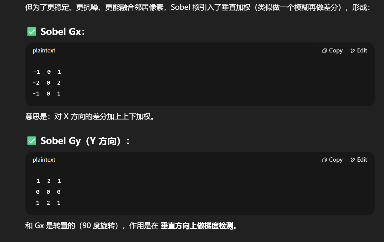
fixed luminance(fixed4 color) {return 0.2125 * color.r + 0.7154 * color.g + 0.0721 * color.b; }half Sobel(v2f i) {const half Gx[9] = {-1, 0, 1,-2, 0, 2,-1, 0, 1};const half Gy[9] = {-1, -2, -1,0, 0, 0,1, 2, 1}; half texColor;half edgeX = 0;half edgeY = 0;for (int it = 0; it < 9; it++) {texColor = luminance(tex2D(_MainTex, i.uv[it]));edgeX += texColor * Gx[it];edgeY += texColor * Gy[it];}half edge = 1 - abs(edgeX) - abs(edgeY);return edge;}它从输入结构体 i 中取出 9 个预先计算好的纹理坐标 i.uv[0~8](分别对应 3x3 的卷积核中心和其八个邻居),并对这些位置执行 Sobel 算法来检测“边缘强度”。
fixed luminance(fixed4 color) {
return 0.2125 * color.r + 0.7154 * color.g + 0.0721 * color.b;
}
这段使用加权平均的方式计算 感知亮度,符合人眼对不同颜色敏感度(绿色最敏感),用于后续 Sobel 处理时不必再处理 RGB,而是用灰度强度。
half texColor;
half edgeX = 0;
half edgeY = 0;
for (int it = 0; it < 9; it++) {
texColor = luminance(tex2D(_MainTex, i.uv[it]));
edgeX += texColor * Gx[it];
edgeY += texColor * Gy[it];
}
这里对 3×3 的采样区域进行遍历,对应位置乘上 Gx/Gy 权重,累加为边缘梯度。
half edge = 1 - abs(edgeX) - abs(edgeY);
计算的是简单的 梯度强度和(L1范数)。
再用 1 - ... 得到“非边缘强度”,所以边缘越强 → 值越小(接近 0),边缘越弱 → 值越接近 1。
你可以把这个值当作亮度返回,绘出边缘线。
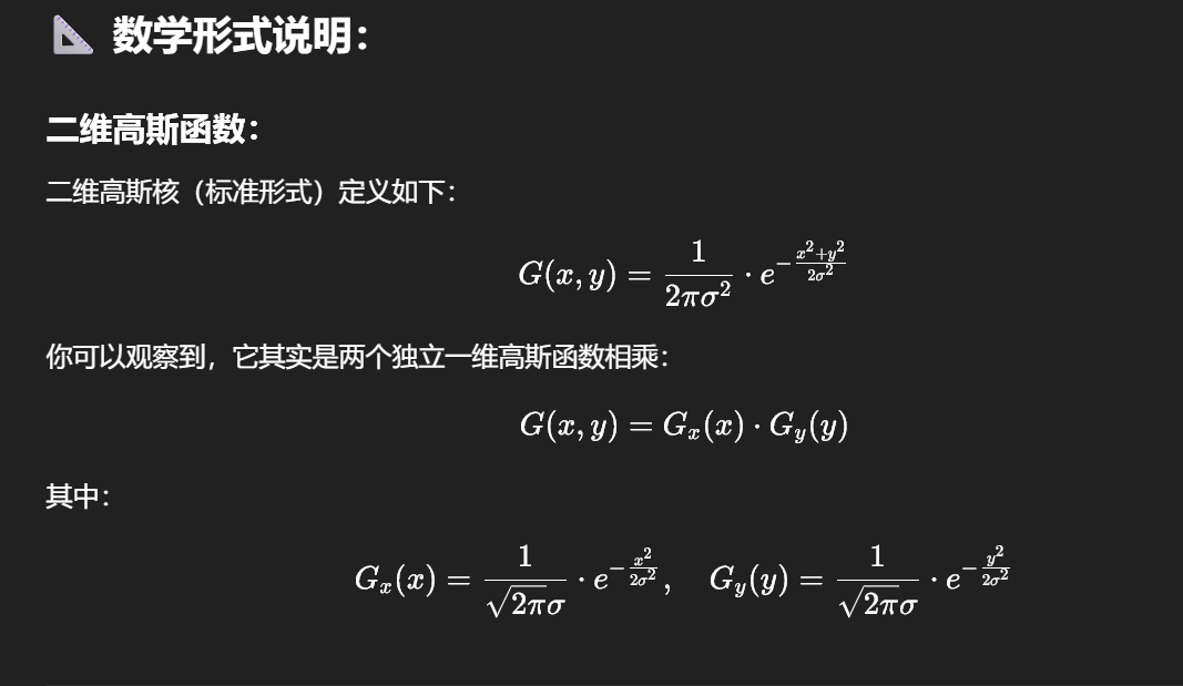
“二维高斯核怎么能变成两个一维高斯核?为什么高斯模糊的结果还能一样?”
高斯核的可分性(Separable Property)
核心结论:
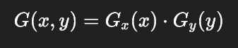
二维高斯核是可分离的,即一个二维的高斯函数可以拆解为两个一维的高斯函数的乘积!
using UnityEngine;
using System.Collections;[ExecuteInEditMode]
[RequireComponent (typeof(Camera))]
public class PostEffectsBase : MonoBehaviour {// Called when startprotected void CheckResources() {bool isSupported = CheckSupport();if (isSupported == false) {NotSupported();}}// Called in CheckResources to check support on this platformprotected bool CheckSupport() {if (SystemInfo.supportsImageEffects == false || SystemInfo.supportsRenderTextures == false) {Debug.LogWarning("This platform does not support image effects or render textures.");return false;}return true;}// Called when the platform doesn't support this effectprotected void NotSupported() {enabled = false;}protected void Start() {CheckResources();}// Called when need to create the material used by this effectprotected Material CheckShaderAndCreateMaterial(Shader shader, Material material) {if (shader == null) {return null;}if (shader.isSupported && material && material.shader == shader)return material;if (!shader.isSupported) {return null;}else {material = new Material(shader);material.hideFlags = HideFlags.DontSave;if (material)return material;else return null;}}
}
只是基类声明,把同用的后处理逻辑都写一起了,实际上对于图像的处理和这些没有关系
d都是子类里,onrenderimage函数,对图像进行处理,在子脚本里创建Material,接受shader用到Material上面,以及这里的函数,截取不透明||中间处理||半透明,然后利用上材质对这里进行处理,
void OnRenderImage (RenderTexture src, RenderTexture dest) {if (material != null) {int rtW = src.width/downSample;int rtH = src.height/downSample;RenderTexture buffer0 = RenderTexture.GetTemporary(rtW, rtH, 0);buffer0.filterMode = FilterMode.Bilinear;Graphics.Blit(src, buffer0);for (int i = 0; i < iterations; i++) {material.SetFloat("_BlurSize", 1.0f + i * blurSpread);RenderTexture buffer1 = RenderTexture.GetTemporary(rtW, rtH, 0);// Render the vertical passGraphics.Blit(buffer0, buffer1, material, 0);RenderTexture.ReleaseTemporary(buffer0);buffer0 = buffer1;buffer1 = RenderTexture.GetTemporary(rtW, rtH, 0);// Render the horizontal passGraphics.Blit(buffer0, buffer1, material, 1);RenderTexture.ReleaseTemporary(buffer0);buffer0 = buffer1;}Graphics.Blit(buffer0, dest);RenderTexture.ReleaseTemporary(buffer0);} else {Graphics.Blit(src, dest);}}OnRenderImage(RenderTexture src, RenderTexture dest) 的调用时机:
是在当前摄像机完成整个一帧的所有渲染(包括不透明、透明、天空盒等所有 passes)之后,马上被调用,用于执行“整屏后处理效果”。
所以 不只是“不透明 pass”之后,而是:
| 阶段 | 是否已完成 |
|---|---|
| 不透明物体 | ✅ 是 |
| 天空盒 | ✅ 是 |
| 半透明/透明物体 | ✅ 是 |
| 所有图像绘制完成 | ✅ 是 |
| OnRenderImage 调用 | 🔜 接下来 |
Unity 5(估计都这样) 中 OnRenderImage() 是引擎级别在摄像机渲染结束后触发的回调:
-
它不在 C# 控制的 Render Loop 中;
-
它不是 CommandBuffer;
-
它没有参数允许你选择“挂载在哪一阶段”。
想“完全控制渲染顺序”的方式:
唯一真正可以“自由插入任意阶段”的机制是:
-
使用 SRP(Scriptable Render Pipeline)
-
比如 URP / HDRP 自定义
RenderFeature、RenderPass
但 Unity 5 并不支持 SRP(那是 Unity 2018.1+ 才引入的)。
void OnRenderImage(RenderTexture src, RenderTexture dest) {if (material != null) {int rtW = src.width;int rtH = src.height;RenderTexture buffer = RenderTexture.GetTemporary(rtW, rtH, 0);// Render the vertical passGraphics.Blit(src, buffer, material, 0);// Render the horizontal passGraphics.Blit(buffer, dest, material, 1);RenderTexture.ReleaseTemporary(buffer);} else {Graphics.Blit(src, dest);}} 典型的 双 pass 高斯模糊(Gaussian Blur) 实现,使用 分离的垂直(vertical)和水平(horizontal)模糊 Pass。
一个 shader 的两个 Pass(第 0 个和第 1 个),对图像先进行垂直方向的模糊,再进行水平方向的模糊,实现高性能、高质量的模糊效果。
void OnRenderImage(RenderTexture src, RenderTexture dest)
这个函数在一帧渲染完后被 Unity 自动调用,src 是当前帧图像,dest 是输出目标(最终屏幕或后处理链的下一个 RenderTexture)。
RenderTexture buffer = RenderTexture.GetTemporary(rtW, rtH, 0);
创建一个临时 RT(buffer)用于中间结果的存储,尺寸与屏幕一致。
Graphics.Blit(src, buffer, material, 0);
将源图像 src 通过 material 的 第 0 个 Pass 处理,结果写入 buffer
这个 Pass 通常是对 Y 方向(垂直方向) 的高斯模糊
Graphics.Blit(buffer, dest, material, 1);
将上一步结果 buffer 再通过 material 的 第 1 个 Pass 处理,结果写入 dest
这个 Pass 对 X 方向(水平方向) 进行模糊
RenderTexture.ReleaseTemporary(buffer);
释放 buffer,避免内存泄漏。
else {
Graphics.Blit(src, dest);
}
如果没有指定 material,则直接把原图 src 输出到 dest,不会有任何后处理。
为什么要用“两次一维模糊”?
高斯核的可分离性:
buffer.filterMode = FilterMode.Bilinear;
是设置这个临时 RenderTexture(buffer)的 采样过滤模式。这是非常关键的优化手段,尤其在**图像缩小(DownSample)**的后处理流程中。
✅ 它的作用是:
让 在模糊 Pass 中采样这个缩小图像时更加平滑,避免锯齿或块状感。
即:采样过程中采用 双线性插值(Bilinear Interpolation),而不是最近点采样(Point)。
| 模式 | 含义 | 用途场景(常见) |
|---|---|---|
Point | 最近点采样(Nearest Neighbor) | 像素风格、无模糊 |
Bilinear | 双线性插值(插值周围 4 像素) | 图像缩放、模糊处理 |
Trilinear | 三线性插值(含 Mipmap 层级) | 3D 模型贴图、含 Mipmap 的情况 |
在这个模糊操作中:
你把 src 从 1920x1080 缩放到比如 480x270,再进行模糊处理。
如果你使用:
-
Point:会导致缩小时像素直接跳变,出现锯齿; -
✅
Bilinear:会在采样时对周围像素做插值,让模糊更自然。
CGINCLUDE 抽象出通用函数/结构,两个 Pass 共享
_BlurSize: 模糊强度倍率,控制采样偏移距离
struct v2f {
float4 pos : SV_POSITION;
half2 uv[5] : TEXCOORD0;
};
一次采样 5 个纹理坐标:
uv[0]: 中心
uv[1~4]: 上下或左右两个方向的 ±1、±2 像素偏移
Pass 流程(在 C# 中调用):
-
Pass 1 垂直方向模糊:
Graphics.Blit(src, buffer, material, 0); -
Pass 2 水平方向模糊:
Graphics.Blit(buffer, dest, material, 1);
通过两次一维模糊,效果等价于一次二维高斯核卷积,但性能提升巨大(从 O(n²) 降为 O(2n))。
使用场景
-
模糊背景(UI、高光)
-
模拟散焦/景深
-
后处理 bloom(结合亮度提取)
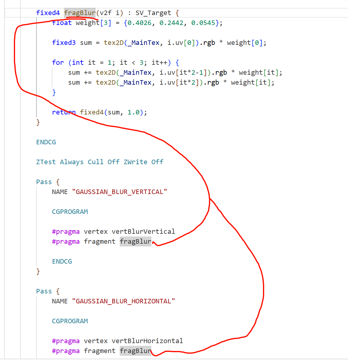
为什么只用了 5 个采样点?
因为每次只在 一个方向上进行卷积:
-
1 个中心点 + 上下或左右方向上各 2 个点(±1、±2 像素偏移) -
共 5 个点:[uv0, uv±1, uv±2]
这是对高斯分布进行的近似采样,采样权重对应的是:
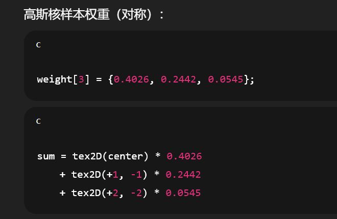
weight[0] = 0.4026 // center
weight[1] = 0.2442 // ±1
weight[2] = 0.0545 // ±2
合起来能很好地逼近二维高斯核:
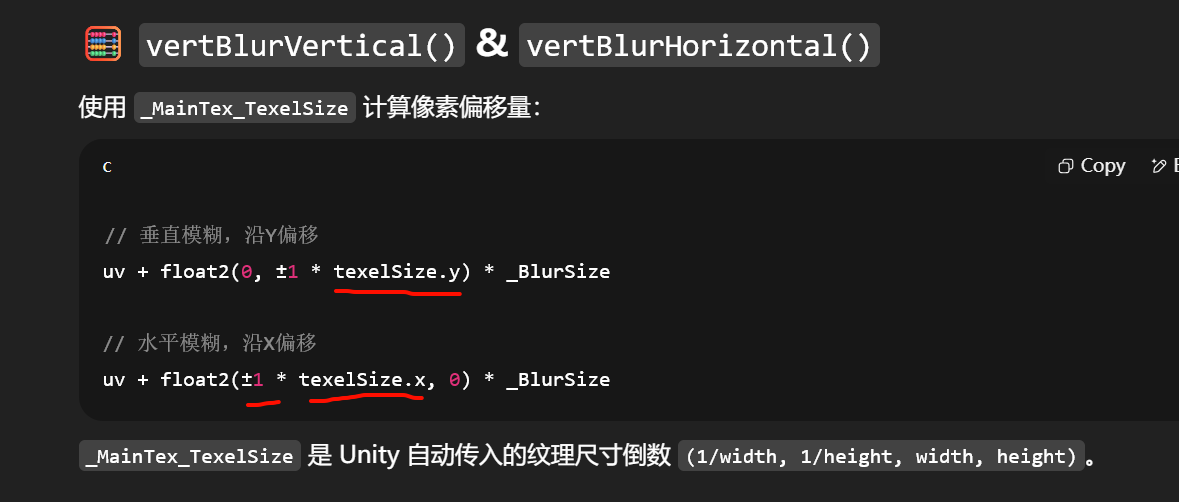
Pass 1:纵向模糊(中心 ±1y ±2y)
Pass 2:横向模糊(中心 ±1x ±2x)
先竖直后水平,是这样的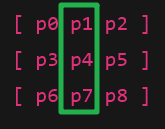
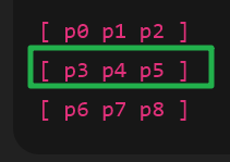
如果是5x5,那也是沿着这一条直线再上下再加一格
如果只是十字,那会漏了边角,这里的技巧就是遍历的时候,自己的边角会被别的像素算上

其他的模糊结果然后参与自己的模糊计算,所以最后 的表现结果就会是正确的