A模块 系统与网络安全 第四门课 弹性交换网络-5
今日目标
- 01 浮动路由
- 02 VRRP基本概念及原理
- 03 VRRP配置
- 04 VRRP负载分担
- 05 多VLAN网关负载分担
- 06 VRRP和MSTP结合应用
1 浮动路由
网络经典故障
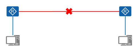
- 单路径场景
√通信终端之间仅仅存在一个转发路径 - 单路径风险
√当这条唯一的路径出现故障,终端之间的通信都会彻底中断
解决方案
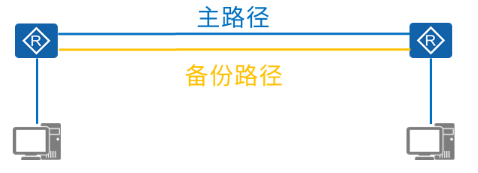
- 冗余路径
√在互联设备之间增加一条冗余路径,实现备份作用。
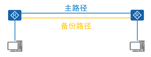
技术实现
- 浮动路由
√也叫浮动静态路由,是一种特殊的静态路由,用于提供一种备份路径。
√当主路径出现故障时,备份路径就会启动,保持网络的连通性。
浮动路由配置命令
- 配置命令
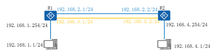
[R1]ip route-static 192.168.4.0 24 192.168.2.2
[R1]ip route-static 192.168.4.0 24 192.168.3.2 Preference 70
配置浮动路由
- 需求描述
√配置接口IP地址
√配置浮动路由,实现路径冗余
√验证浮动路由的效果
2 VRRP基本概念及原理
网络经典故障
- 单网关场景分析
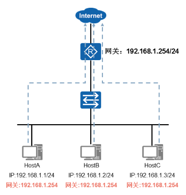
- 单网关面临的问题
√当网关故障后,网段中的主机无法上网
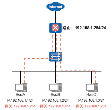
解决方案
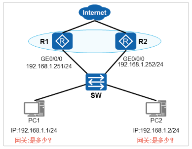
- 通过部署多网关的方式实现网关的备份
- 存在的问题
√如何定义主机的网关地址
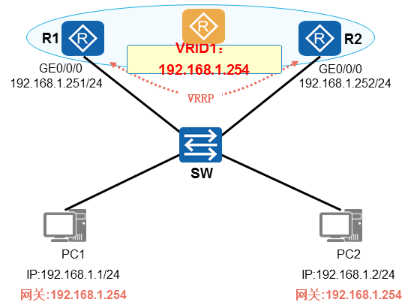
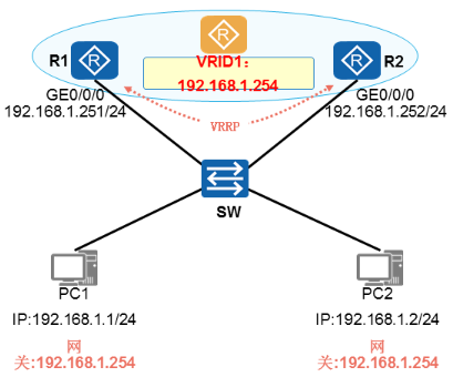
技术实现
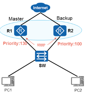
- VRRP
√把多台路由设备联合组成一台虚拟的路由器配置一个虚拟网关P地址
√虚拟网关P地址作为主机的网关,实现网关的备份
VRRP概述
- VRRP协议
√Virtual Router Redundancy Protocol,虚拟路由器冗余协议
√由IETF标准RFC2338定义,是公有标准协议,任何厂商设备都支持
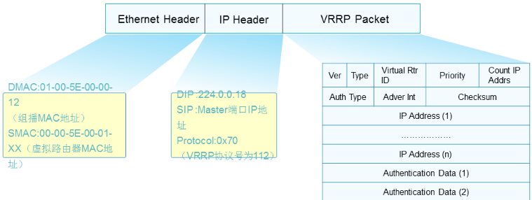
√VRRP协议位于OSl模型第三层,协议号为112
√VRRP发送报文的方式为组播,地址为224.0.0.18
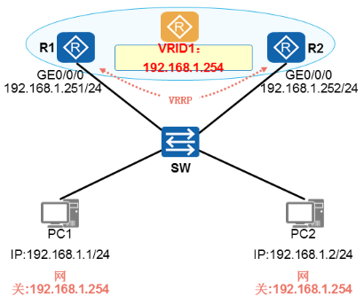
VRRP基本概念
- VRRP路由器:
√运行VRRP协议的路由器称为VRRP路由器,如:R1和R2。
√VRRP是配置在路由器的接口上的,而且也是基于接口来工作的。
- VRID:Virtual Router Identifier(虚拟路由标识符)
√ 一个VRRP组由多台路由器(的接口)组成,用相同的VRID进行标识。
√ 同一个VRRP组的路由器之间交互VRRP协议报文产生一台虚拟路由器。
√ 一个VRRP组中只能出现一台Master路由器。 - 虚拟路由器:
√ 每一个VRRP组中都会产生一台虚拟路由器(Virtual Router),该路由器并非真实存在的物理设备,而是由VRRP虚以出来的逻辑设备。
√ 一个VRRP组只产生一台虚拟路由器。
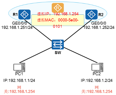
- 虚拟IP地址及虚拟MAC地址:
√ 虚拟路由器拥有引P地址和MAC地址
√ 其中IP地址由管理员配置VRRP时指定
√ 虚拟IP地址通常作为用户主机的网关地址
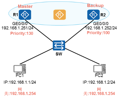
- Masteri路由器
√ Masteri路由器,也被称为主路由器
√ 负责转发用户上网数据 - Backup路由器
√ 也被称为备份路由器
√ 负责监控主路由器状态 - Priority
√ 优先级值
√ 用来选举Master路由器
√ 数值越大越优先
- Masteri路由器
√ Masteri路由器,负责转发用户上网数据。
√ Masterf路由器会周期性地发送VRRP报文,用于通知同一个VRRP组中的Backup路由器关于自己的存活状态。 - Backup路由器
√ Backup路由器会实时侦听Masterf路由器发送出来的VRRP报文。
√ 当Masteri路由器故障时,Backup路由器会接替Masteri路由器的工作,称为新的Master路由器,负责转发用户上网数据。 - Priority
√ 优先级值,使用优先级来选举Master路由器和Backupi路由器
√ 优先级取值范围0-255,数值越大越优先
√ 如果优先级数值相等则比较接口P地址大小,P地址值越大越优先
VRRP协议报文
√ VRRP协议报文基于组播方式发送,因此只能在同一个广播域传递
√ VRRP协议报文的目的组播地址为224.0.0.18
√ VRRP协议封装在IP报头后面,协议号为112
VRRP技术原理
VRRP主备选举
- VRRP协议状态机
√ Initialize(初始状态)
√ Master(活动状态)
√ Backup(备份状态)
VRRP主备选举
√ 配置完VRRP的设备初始时默认Initialize状态。
√ 若设备优先级小于255,则会先切换至Backup状态,然后再切换至Master状态。
√ R1和R2通过相互发送VRRP报文进行Master选举。
√ R1的优先级为200,所以被选为Masteri路由器。
√ RI被选举为Masteri路由器后,立即发送免费ARP报文将虚拟MAC地址通告给与它连接的设备和主机。
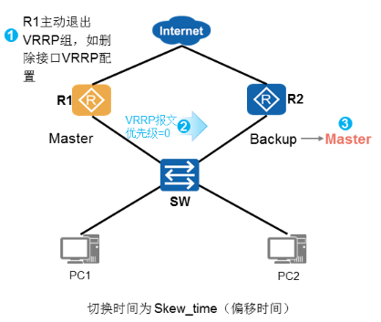
VRRP主备切换
√ R1-Master设备删除配置
√ R1-Master发送优先级为0的报文
√ R2-Backup设备成为新的Master
√ 切换时间为偏移时间
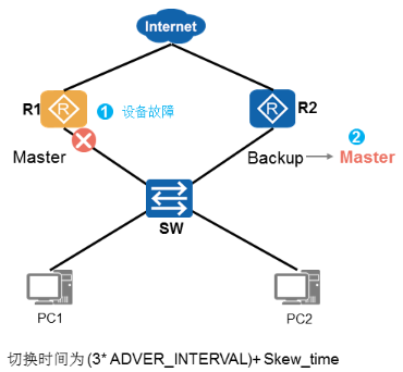
√ R1-Master设备故障,无法发报文
√ R2-Backup设备等待定时器超时后
√ R2-Backup设备成为新的Master
VRRP定时器
- VRRP两个定时器
√ ADVER INTERVAL定时器:Master发送VRRP通告报文时间周期,默认值为l秒。
√ MASTER DOWN定时器:Backup设备监听该定时器超时后,会变为Master状态。
√ MASTER DOWN定时器计算公式如下:- MASTER DOWN=(3*ADVER_INTERVAL)+Skew_time(偏移时间)
- 其中,Skew_Time=(256-Priority)/256
VRRP主备回切
√ R1从故障恢复后,重新进行主备选举
√ R1的优先级为130,大于R2
√ 且R1开启了抢占模式
√ R1又重新成为Master设备
VRRP抢占
- VRRP抢占模式:
√ 抢占模式(默认开启):如果Backup路由器开启了抢占功能,那么当它发现Masteri路由器的优先级比自己更低时,它将立即切换至Master状态,成为新的Masteri路由器。 - 非抢占模式:
√ 如果Backup路由器没有开启抢占功能,那么即使它发现Master路由器的优先级比自己更低,也只能依然保持Backup状态。
VRRP工作原理
- VRRP工作过程
√ VRRP备份组中的设备根据优先级选举出Master-主路由器
√ Master-主路由器,承担数据转发任务
√ Master-主路由器,周期性发送VRRP通告报文(三层心跳报文)
√ 通告报文发送的周期时间:默认情况下是1秒
√ 通告报文发送的目的地址是组播地址:224.0.0.18
√ Backup-备份路由器,监控“主路由器”状态,在3倍的“发送周期”后,如果无法收到“主路由器”发送的VRRP通告报文,备份路由器升级为“新的Master-主路由器”承担流量转发任务
3 VRRP配置
VRRP配置命令
- 配置命令
[R1]interface g0/0/0
[R1-G0/0/0]ip address 192.168.1.251 24
[R1-G0/0/0]vrrp vrid 1 virtual-ip 192.168.1.254     //配置VRRP虚拟网关地址
[R1-G0/0/0]vrrp vrid 1 priority 130                 //配置VRRP优先级
[R2]interface g0/0/0
[R2-G0/0/0]ip address192.168.1.252 24
[R2-G0/0/0]vrrp vrid 1 virtual-ip 192.168.1.254
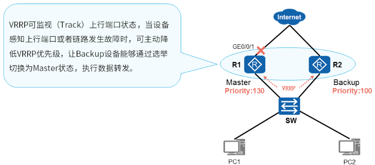
VRRP监视上行端口
VRRP监视上行端口配置
- 配置命令
[R1-G0/0/0]vrrp vrid 1 track interface GigabitEthernet 0/0/1 reduced 50 #如果R1的g0/0/1接口状态为down那么VRRP的优先级就减去50
上行端口故障恢复
- 主路由器故障链路或端口恢复
√ 主路由器发送的优先级,恢复为130
√ 主路由器抢占回“Master’”身份,继续“转发用户流量” - VRRP默认开启抢占功能
√ VRRP在主路由器设备上,必须开启
VRRP监控上行接口
- 需求
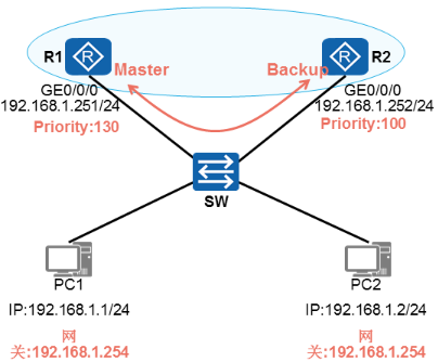
√ R1/R2部署VRRP备份组,组号为1
√ R1的VRRP优先级为130,R1是主路由器
√ R2的VRRP优先级为100,R2是备份设备
√ PC1和PC2互通,流量走R1-主设备
√ R1连接R3的上行链路故障后自动降低自身优先级
√ R2升级为主设备,承担流量转发
4 VRRP负载分担
VRRP单组缺陷
- 如果每个网段只有一个VRRP备份组:
√ 主路由器数据转发压力大
√ 备份路由器不转发任何数据
√ 网络设备利用率低
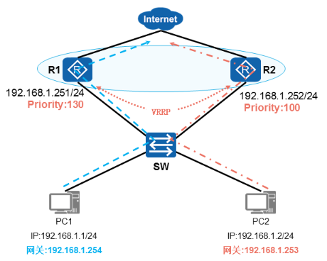
VRRP负载分担
- VRRP负载分担
√ 创建多个备份组
√ 每个备份组中都选举Master
√ 实现流量转发的负载分担
VRRP负载均衡配置
- 配置VRRP备份组1
[R1]interface g0/0/0
[R1-G0/0/0]ip address 192.168.1.251 24
[R1-G0/0/0]vrrp vrid 1 virtual-ip 192.168.1.254
[R1-G0/0/0]vrrp vrid 1 priority 130
[R1-G0/0/0]vrrp vrid 1 track int g0/0/1 reduced 50[R2]interface g0/0/0
[R2-G0/0/0]ip address 192.168.1.252 24
[R2-G0/0/0]vrrp vrid 1 virtual-ip 192.168.1.254
- 配置VRRP备份组2
[R1]interface g0/0/0
[R1-G0/0/0]ip address192.168.1.251 24
[R1-G0/0/0]vrrp vrid 2 virtual-ip 192.168.1.253[R2]interface g0/0/0
[R2-G0/0/0]ip address192.168.1.252 24
[R2-G0/0/0]vrrp vrid 2 virtual-ip 192.168.1.253
[R2-G0/0/0]vrrp vrid 2 priority 130
[R2-G0/0/0]vrrp vrid 2 track int g0/0/1 reduced 50
练习:
VRRP负载分担
- 需求
- 实现流量转发的负载分担
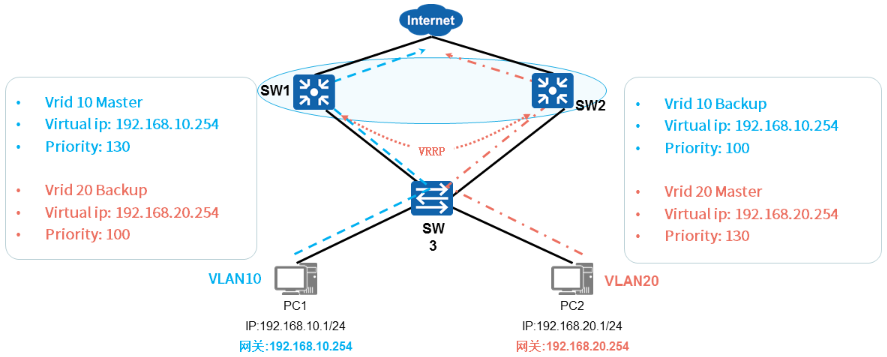
5 多VLAN网关负载分担
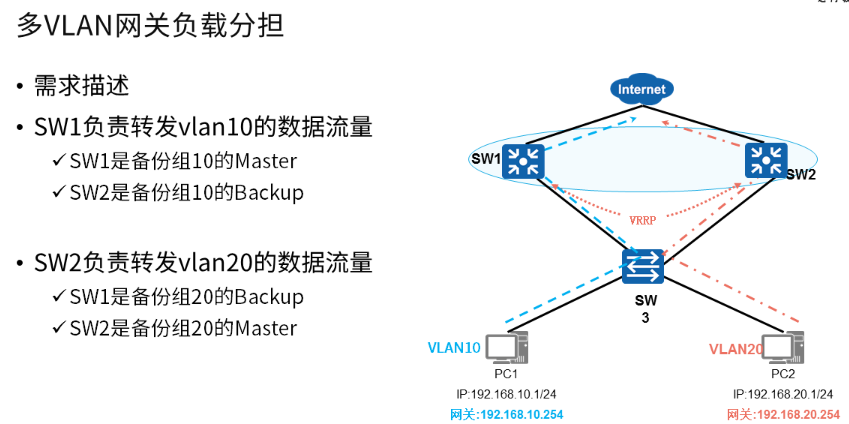
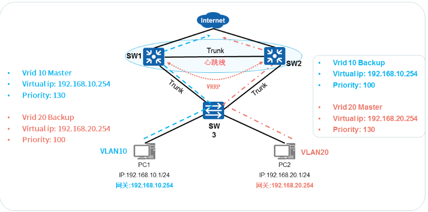
- 多VLAN网关负载分担
√ 创建多个备份组,每个备份组都有一台虚拟路由器
√ 每个物理路由器在不同的VRRP组中扮演不同的角色
√ 不同的虚拟路由器的VirtualIP作为不同的内网网关地址,实现流量转发负载分担
在这里插入图片描述
配置 VRRP备份组10
- 创建VRRP备份组10,负责转发VLAN10的数据
- SW1在备份组10中的优先级为130,为Master设备
- SW2 在 备份组10中的优先级为100,为Backup设备
- 备份组10的虚拟IP为192.168.10.254,所以VLAN10内主机的网关IP:192.168.10.254
配置 VRRP 备份组20
- 创建VRRP备份组20,负责转发VLAN20的数据
- SW1在 备份组20中的优先级为100,为Backup设备
- SW2 在备份组20中的优先级为130,为Master设备
- 备份组20的虚拟IP为192.168.20.254,所以VLAN20内主机的网关IP:192.168.20.254
VRRP负载均衡配置
- 配置 VRRP备份组10
[SWl]interface vlanif 10
[SW1-Vlanif10]ip address 192.168.10.251 24
[SW1-Vlanif10]vrrp vrid 10 virtual-ip 192.168.10.254
[SW1-Vlanif10]vrrp vrid 10 priority 130[SW2lint vlanif 10
[SW2-Vlanif10]ip address 192.168.10.252 24
[SW2-Vlanif10]vrrp vrid 10 virtual-ip 192.168.10.254
- 配置 VRRP备份组20
[SW1]interface vlanif 20
[SW1-Vlanif20]ip address 192.168.20.251 24
[SW1-Vlanif20]vrrp vrid 10 virtual-ip 192.168.20.254[SW2]int vlanif 20
[SW2-Vlanif20]ip address 192.168.20.252 24
[SW2-Vlanif20]vrrp vrid 20 virtual-ip 192.168.20.254
[SW1-Vlanif20]vrrp vrid 20 priority 130
6 VRRP和MSTP结合应用
VRRP与MSTP结合应用
- 配置 VRRP备份组10
√ 创建VRRP备份组10,负责转发VLAN10的数据 - 配置 VRRP 备份组20
√ 创建VRRP备份组20,负责转发VLAN20的数据 - 配置VRRP和MSTP联动
√ VRRP+MSTP可以在实现负载分担的同时保证网络冗余备份
配置实例:
1 配置浮动路由
1.1 问题
1)配置接口IP地址
2)配置浮动路由,实现链路的冗余
3)验证浮动路由的效果
1.2 方案
使用eNSP搭建实验环境,如图-1所示。
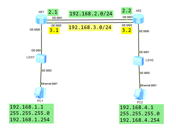
图-1
1.3 步骤
实现此案例需要按照如下步骤进行。
1)配置终端设备 PC-1 和 PC-2
PC-1 IP 地址: 192.168.1.1255.255.255.0192.168.1.254PC-2 IP 地址:192.168.4.1255.255.255.0192.168.4.254
2)配置网络设备 – SW1
<Huawei>system-view             // 进入系统视图
[Huawei]sysname SW1           // 修改设备名称为 SW1
3)配置网络设备 – SW2
<Huawei>system-view             // 进入系统视图
[Huawei]sysname SW2           // 修改设备名称为 SW2
4)配置网络设备 – R1
<Huawei>system-view
[Huawei]sysname R1
[R1]interface GigabitEthernet 0/0/0                  // PC-1的网关接口
[R1-GigabitEthernet0/0/0]ip address 192.168.1.254 24
[R1-GigabitEthernet0/0/0]quit
[R1]interface GigabitEthernet 0/0/1                  // R1-R2之间的主链路
[R1-GigabitEthernet0/0/1]ip address 192.168.2.1 24
[R1-GigabitEthernet0/0/1]quit
[R1]interface GigabitEthernet 0/0/2                  // R1-R2之间的备份链路
[R1-GigabitEthernet0/0/2]ip address 192.168.3.1 24
[R1-GigabitEthernet0/0/2]quit
5)配置网络设备 - R2
<Huawei>system-view
[Huawei]sysname R2
[R2]interface GigabitEthernet 0/0/0                  // PC-2的网关接口
[R2-GigabitEthernet0/0/0]ip address 192.168.4.254 24
[R2-GigabitEthernet0/0/0]quit
[R2]interface GigabitEthernet 0/0/1                  // R2-R1之间的主链路
[R2-GigabitEthernet0/0/1]ip address 192.168.2.2 24
[R2-GigabitEthernet0/0/1]quit
[R2]interface GigabitEthernet 0/0/2                  // R2-R1之间的备份链路
[R2-GigabitEthernet0/0/2]ip address 192.168.3.2 24
[R2-GigabitEthernet0/0/2]quit
6)配置浮动静态路由 - R1
[R1]ip route-static 192.168.4.0 255.255.255.0 192.168.2.2   // 主链路对应的路由
[R1]ip route-static 192.168.4.0 255.255.255.0 192.168.3.2 preference 100
7)配置浮动静态路由 - R2
[R2]ip route-static 192.168.1.0 255.255.255.0 192.168.2.1   // 主链路对应的路由
[R2]ip route-static 192.168.1.0 255.255.255.0 192.168.3.1 preference 100
8)测试
PC-1:Ping 192.168.4.1 -t // 一直向 192.168.4.1 发送 ping 包- 可以访问成功,R1使用的主链路对应的路由条目- 断开 R1 的 Gi0/0/1 接口,依然可以访问成功;使用的是备份链路对应路由条目
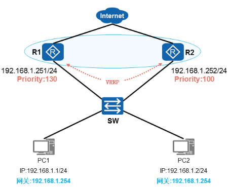
2 配置VRRP热备
2.1 问题
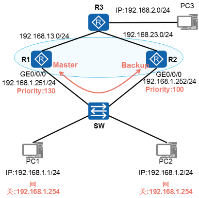
1)R1/R2部署VRRP备份组,组号为1
2)R1的VRRP优先级为130,R1是主路由器
3)R2的VRRP优先级为100,R2是备份设备
4)PC1和PC2互通,流量走R1-主设备
2.2 方案
搭建实验环境,如图-2所示。
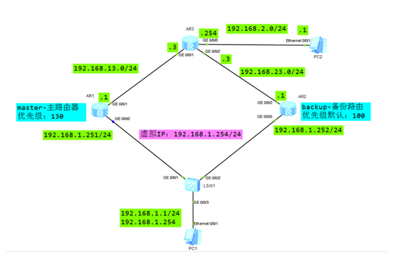
图-2
2.3 步骤
实现此案例需要按照如下步骤进行。
1)配置PC的IP地址,掩码,网关
2)R1/R2配置接口IP地址,配置VRRP
PC-1 IP 地址: 192.168.1.1255.255.255.0192.168.1.254 // 后期通过 VRRP 形成的 虚拟网关IP
3)R1/R2配置接口IP地址,配置VRRP
R1配置:
[Huawei]sys R1
[R1]int g0/0/0
[R1-G0/0/0]ip address 192.168.1.251 24
[R1-G0/0/0]vrrp vrid 1  virtual-ip  192.168.1.254
[R1-G0/0/0]vrrp vrid 1 priority 130
[R1-G0/0/0]int g0/0/1
[R1-G0/0/1]ip address 192.168.13.1 24
R2配置:
[Huawei]sys R2
[R2]int g0/0/0
[R2-G0/0/0]ip address 192.168.1.252 24
[R2-G0/0/0]vrrp vrid 1  virtual-ip  192.168.1.254
[R2-G0/0/0]int g0/0/2
[R2-G0/0/2]ip address 192.168.23.1 24
4)R1/R2/R3配置静态路由
R1配置:
[R1]ip route-static 192.168.2.0 24 192.168.13.3
R2配置:
[R2]ip route-static 192.168.2.0 24 192.168.23.3
R3配置:
[Huawei]sys R3
[R3]int g0/0/1
[R3-G0/0/1]ip address 192.168.13.3 24
[R3-G0/0/1]int g0/0/2
[R3-G0/0/2]ip address 192.168.23.3 24
[R3-G0/0/2]int g0/0/0
[R3-G0/0/0]ip address 192.168.2.254 24
[R3-Gt0/0/0]quit
[R3]ip route-static  192.168.1.0  24 192.168.13.1
[R3]ip route-static  192.168.1.0  24 192.168.23.1
5)验证VRRP
<R1>display vrrp     //查看详细信息
<R1>display vrrp brief     //查看简要信息
PC1 -->ping     192.168.2.1
PC1 -->tracert  192.168.2.1    //验证数据报文是否经主路由器转发
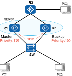
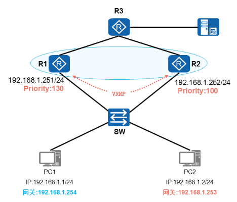
3 VRRP链路跟踪
3.1 问题
1)配置接口IP地址
2)配置 VRRP 主备网关
3)配置 VRRP 链路跟踪
4)断开 R1 G0/0/1 查看 VRRP 状态
3.2 方案
搭建实验环境,如图-3所示。
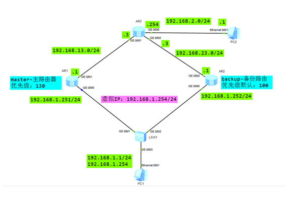
图-3
3.3 步骤
实现此案例需要按照如下步骤进行。
1)配置终端设备 PC1
PC-1 IP 地址: 192.168.1.1255.255.255.0192.168.1.254 // 后期通过 VRRP 形成的 虚拟网关IPPC-2 IP 地址: 192.168.2.1255.255.255.0192.168.2.254 // R3的网关接口IP地址
2)R1/R2配置接口IP地址,配置VRRP,R1为主路由器,R2为备份路由器
R1配置:
[R1]int g0/0/0
[R1-G0/0/0]ip address 192.168.1.251 24
[R1-G0/0/0]vrrp vrid 1  virtual-ip  192.168.1.254
[R1-G0/0/0]vrrp vrid 1 priority 130
[R1-G0/0/0]int g0/0/1
[R1-G0/0/1]ip address 192.168.13.1 24
R2配置:
[R2]int g0/0/0
[R2-G0/0/0]ip address 192.168.1.252 24
[R2-G0/0/0]vrrp vrid 1  virtual-ip  192.168.1.254
[R2-G0/0/0]int g0/0/2
[R2-G0/0/2]ip address 192.168.23.1 24
3)R1/R2/R3配置静态路由
R1配置:
[R1]ip route-static 192.168.2.0 24 192.168.13.3
R2配置:
[R2]ip route-static 192.168.2.0 24 192.168.23.3
R3配置:
[R3]int g0/0/1
[R3-G0/0/1]ip address 192.168.13.3 24
[R3-G0/0/1]int g0/0/2
[R3-G0/0/2]ip address 192.168.23.3 24
[R3-G0/0/2]int g0/0/0
[R3-G0/0/0]ip address 192.168.2.254 24
[R3-Gt0/0/0]quit
[R3]ip route-static  192.168.1.0  24 192.168.13.1
[R3]ip route-static  192.168.1.0  24 192.168.23.1
4)验证VRRP
<R1>display vrrp                //查看详细信息
<R1>display vrrp brief         //查看简要信息
<R2>display vrrp                //查看详细信息
<R2>display vrrp brief         //查看简要信息
PC1 -->ping     192.168.2.1
PC1 -->tracert  192.168.2.1    //验证数据报文是否经主路由器转发
5)模拟R1上行链路故障,验证结果
[R1]int g0/0/1
[R1-GigabitEthernet0/0/1]shutdown   //模拟R1的g0/0/1口链路故障
<R1>display vrrp                //查看R1的状态,上行链路down掉后,R1是否还是Master设备
<R2>display vrrp                //查看R2的状态
PC1 -->ping     192.168.2.1    //验证是否出现故障,是否能够正常通信
6)配置 R1 的 VRRP 链路跟踪
[R1-G0/0/0]vrrp vrid 1 track interface GigabitEthernet 0/0/1 reduced 50
7)把R1的上行链路接口g0/0/1 shutdown 掉,验证R2是否会升级为 master
<R1>display vrrp     //查看R1的状态
<R2>display vrrp     //查看R2的状态,R1上行接口(链路)down掉后,R2是否升级为新的Master
PC1 -->ping     192.168.2.1
PC1 -->tracert  192.168.2.1    //验证数据报文转发路径
4 VRRP负载分担
4.1 问题
1)R1/R2部署VRRP,创建两个VRRP备份组,分别为组1和组2
2)在备份组1中为R1为Master-主路由器、R2为Backup-备份路由器
3)在备份组2中为R2为Master-主路由器、R1为Backup-备份路由器
4)PC1和Server1通信,数据默认通过备份组1中的R1-Master转发,如果R1故障,依靠备份组1内的R2转发
5)PC2和Server1通信,数据默认通过备份组2中的R2-Master转发,如果R2故障,依靠备份组2内的R1转发
4.2 方案
搭建实验环境,如图-4所示。
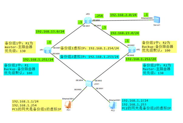
图-4
4.3 步骤
实现此案例需要按照如下步骤进行。
1)配置PC和server的IP地址,掩码,网关
PC-1 IP 地址: 192.168.1.1255.255.255.0192.168.1.254 PC-2 IP 地址: 192.168.1.2255.255.255.0192.168.1.254 Server-1 IP 地址: 192.168.2.1255.255.255.0192.168.2.254
2)R1/R2配置接口IP地址,配置VRRP
R1配置:
[R1]int g0/0/1
[R1-G0/0/1]ip address 192.168.13.1 24
[R1-G0/0/1]int g0/0/0
[R1-G0/0/0]ip address 192.168.1.251 24
[R1-G0/0/0]vrrp vrid 1 virtual-ip 192.168.1.254
[R1-G0/0/0]vrrp vrid 1 priority 130
[R1-G0/0/0]vrrp vrid 1 track int g0/0/1 reduced 50
[R1-G0/0/0]vrrp vrid 2 virtual-ip 192.168.1.253
R2配置:
[R2]int g0/0/2
[R2-G0/0/2]ip address 192.168.23.1 24
[R2-G0/0/2]int g0/0/0
[R2-G0/0/0]ip address 192.168.1.252 24
[R2-G0/0/0]vrrp vrid 1 virtual-ip 192.168.1.254
[R2-G0/0/0]vrrp vrid 2 virtual-ip 192.168.1.253
[R2-G0/0/0]vrrp vrid 2 priority 130
[R2-G0/0/0]vrrp vrid 2 track int g0/0/2 reduced 50
3)R1/R2/R3配置静态路由
R3配置:
[R3]int g0/0/0
[R3-G0/0/0]ip address 192.168.2.254 24
[R3-Gi0/0/0]int g0/0/1
[R3-G0/0/1]ip address 192.168.13.3 24
[R3-G0/0/1]int g0/0/2
[R3-G0/0/2]ip address 192.168.23.3 24
[R3-G0/0/2]quit
[R3]ip route-static 192.168.1.0  24  192.168.13.1
[R3]ip route-static 192.168.1.0  24  192.168.23.1   preference 70
R1配置静态路由:
[R1]ip route-static 192.168.2.0 24 192.168.13.3
R2配置静态路由:
[R2]ip route-static 192.168.2.0 24 192.168.23.3
4)验证VRRP
PC1>tracert 192.168.2.11  192.168.1.251   31 ms  47 ms  47 ms2  192.168.13.3   31 ms  47 ms  47 ms3  192.168.2.1   63 ms  46 ms  47 ms
PC2>tracert 192.168.2.11  192.168.1.252   32 ms  47 ms  46 ms2  192.168.23.3   47 ms  32 ms  62 ms3  192.168.2.1   47 ms  47 ms  31 ms
5 VRRP负载分担-多VLAN环境
5.1 问题
1)PC1属于vlan10 ,PC2属于vlan20
2)vlan10的主网关是SW1,备份网关是SW2,vlan10的数据流量默认由SW1转发
3)vlan20的主网关是SW2,备份网关是SW1,vlan20的数据流量默认由SW2转发
5.2 方案
搭建实验环境,如图-5所示。
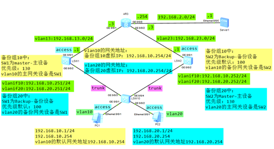
图-5
5.3 步骤
实现此案例需要按照如下步骤进行。
1)配置PC和server的IP地址,掩码,网关
2)SW10交换机配置
[SW10]vlan batch 10 20
[SW10]int g0/0/1
[SW10-G0/0/1]port link-type access
[SW10-G0/0/1]port default vlan 10
[SW10-G0/0/1]int g0/0/2
[SW10-G0/0/2]port link-type access
[SW10-G0/0/2]port default vlan 20
[SW10-G0/0/2]quit
[SW10]port-group group-member g0/0/3 g0/0/4
[SW10-port-group]port link-type trunk
[SW10-port-group]port trunk allow-pass vlan all
3)SW1和SW2配置VRRP负载均衡
SW1配置:
[SW1]vlan batch 10 20 13
[SW1]int g0/0/1
[SW1-G0/0/1]port link-type access
[SW1-G0/0/1]port default vlan 13
[SW1-G0/0/1]quit
[SW1]int vlanif 13
[SW1-Vlanif13]ip address 192.168.13.1 24
[SW1-Vlanif13]int vlanif 10
[SW1-Vlanif10]ip address 192.168.10.251 24
[SW1-Vlanif10]vrrp vrid 10 virtual-ip 192.168.10.254
[SW1-Vlanif10]vrrp vrid 10 priority 130
[SW1-Vlanif10]vrrp vrid 10 track int g0/0/1 reduced 50
[SW1-Vlanif10]int vlanif 20
[SW1-Vlanif20]ip address 192.168.20.251 24
[SW1-Vlanif20]vrrp vrid 20 virtual-ip 192.168.20.254
[SW1-Vlanif20]quit
[SW1]int g0/0/2
[SW1-G0/0/2]port link-type trunk
[SW1-G0/0/2]port trunk allow-pass vlan all
SW2配置:
[SW2]vlan batch 10 20 23
[SW2]int g0/0/1
[SW2-G0/0/1]port link-type access
[SW2-G0/0/1]port default vlan 23
[SW2-G0/0/1]quit
[SW2]int vlanif 23
[SW2-Vlanif23]ip address 192.168.23.1 24
[SW2-Vlanif23]int vlanif 10
[SW2-Vlanif10]ip address 192.168.10.252 24
[SW2-Vlanif10]vrrp vrid 10 virtual-ip 192.168.10.254
[SW2-Vlanif10]int vlanif 20
[SW2-Vlanif20]ip address 192.168.20.252 24
[SW2-Vlanif20]vrrp vrid 20 virtual-ip 192.168.20.254
[SW2-Vlanif20]vrrp vrid 20 priority 130
[SW2-Vlanif20]vrrp vrid 20 track int g0/0/1 reduced 50
[SW2-Vlanif20]quit
[SW2]int g0/0/2
[SW2-G0/0/2]port link-type trunk
[SW2-G0/0/2]port trunk allow-pass vlan all
4)SW1/SW2/R3配置静态路由
R1配置:
[R1]int g0/0/0
[R1-G0/0/0]ip address 192.168.2.254 24
[R1-G0/0/0]int g0/0/1
[R1-G0/0/1]ip address 192.168.13.3 24
[R1-G0/0/1]int g0/0/2
[R1-G0/0/2]ip address 192.168.23.3 24
[R1-G0/0/2]quit
[R1]ip route-static 192.168.10.0 24 192.168.13.1
[R1]ip route-static 192.168.10.0 24 192.168.23.1    preference 70
[R1]ip route-static 192.168.20.0 24 192.168.13.1    preference 70
[R1]ip route-static 192.168.20.0 24 192.168.23.1
SW1配置:
[SW1]ip route-static 192.168.2.0 24 192.168.13.3
SW2配置:
[SW2]ip route-static 192.168.2.0 24 192.168.23.3
5)验证VRRP
PC1 ping  server1 验证vlan10的数据依靠SW1转发
PC2 ping  server1 验证vlan20的数据依靠SW2转发
PC1>tracert 192.168.2.11  192.168.10.251   47 ms  32 ms  46 ms2  192.168.13.3   63 ms  62 ms  79 ms3  192.168.2.1   62 ms  63 ms  62 ms
PC2>tracert 192.168.2.11  192.168.20.252   109 ms  47 ms  31 ms2  192.168.23.3   110 ms  78 ms  78 ms3  192.168.2.1   94 ms  78 ms  93 ms
[SW1]display vrrp brief
VRID  State        Interface                Type     Virtual IP
----------------------------------------------------------------
10    Master       Vlanif10                 Normal   192.168.10.254
20    Backup       Vlanif20                 Normal   192.168.20.254
----------------------------------------------------------------
Total:2     Master:1     Backup:1     Non-active:0
[SW2]display vrrp brief
VRID  State        Interface                Type     Virtual IP
----------------------------------------------------------------
10    Backup       Vlanif10                 Normal   192.168.10.254
20    Master       Vlanif20                 Normal   192.168.20.254
----------------------------------------------------------------
Total:2     Master:1     Backup:1     Non-active:0
6 VRRP与MSTP结合应用
6.1 问题
1)PC1属于vlan10 ,PC2属于vlan20
2)vlan10的主网关是SW1,备份网关是SW2,vlan10的数据流量默认由SW1转发
3)vlan20的主网关是SW2,备份网关是SW1,vlan20的数据流量默认由SW2转发
4)SW1和SW2部署MSTP和VRRP,既要实现负载分担,又要互为备份
6.2 方案
搭建实验环境,如图-2所示。
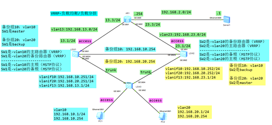
图-2
6.3 步骤
实现此案例需要按照如下步骤进行。
1)配置PC和server的IP地址,掩码,网关
2)SW3交换机配置
SW3配置:
[SW3]vlan batch 10 20
[SW3]int g0/0/1
[SW3-GigabitEthernet0/0/1]port link-type access
[SW3-GigabitEthernet0/0/1]port default vlan 10
[SW3-GigabitEthernet0/0/1]int g0/0/2
[SW3-GigabitEthernet0/0/2]port link-type access
[SW3-GigabitEthernet0/0/2]port default vlan 20
[SW3-GigabitEthernet0/0/2]quit
[SW3]port-group group-member g0/0/3 g0/0/4
[SW3-port-group]port link-type trunk
[SW3-port-group]port trunk allow-pass vlan all
[SW3-port-group]quit
[SW3]stp region-configuration
[SW3-mst-region] region-name ntd
[SW3-mst-region] instance 10 vlan 10
[SW3-mst-region] instance 20 vlan 20
[SW3-mst-region] active region-configuration
3)SW1和SW2配置VRRP和MSTP和静态路由
SW1配置:
[SW1]vlan batch 10 20 13
[SW1]int g0/0/2
[SW1-GigabitEthernet0/0/2]port link-type trunk
[SW1-GigabitEthernet0/0/2]port trunk allow-pass vlan all
[SW1-GigabitEthernet0/0/2]qui
[SW1]vlan batch 13
[SW1]int vlanif 10
[SW1-Vlanif10]ip address 192.168.10.251 24
[SW1-Vlanif10]int vlanif 20
[SW1-Vlanif20]ip address 192.168.20.251 24
[SW1-Vlanif20]int vlanif 13
[SW1-Vlanif13]ip address 192.168.13.1 24
[SW1-Vlanif13]quit
[SW1]int vlanif10
[SW1-Vlanif10]vrrp vrid 10 virtual-ip 192.168.10.254
[SW1-Vlanif10]vrrp vrid 10 priority 130
[SW1-Vlanif10]vrrp vrid 10 track int g0/0/1 reduced 50
[SW1-Vlanif10]int vlanif 20
[SW1-Vlanif20]vrrp vrid 20 virtual-ip 192.168.20.254
[SW1-Vlanif20]quit
[SW1]int g0/0/1
[SW1-GigabitEthernet0/0/1]port link-type access
[SW1-GigabitEthernet0/0/1]port default vlan 13
[SW1-GigabitEthernet0/0/1]quit
[SW1]ip route-static 192.168.2.0 24 192.168.13.3
[SW1]stp region-configuration    //配置MSTP
[SW1-mst-region]region-name ntd
[SW1-mst-region]instance 10 vlan 10
[SW1-mst-region]instance 20 vlan 20
[SW1-mst-region]active region-configuration
[SW1-mst-region]quit
[SW1]stp instance 10 priority 4096   //让SW1成为vlan10的主根
[SW1]stp instance 20 priority 8192   //让SW1成为vlan20的备根
[SW1]int g0/0/24
[SW1-GigabitEthernet0/0/24]port link-type trunk
[SW1-GigabitEthernet0/0/24]port trunk allow-pass vlan all
SW2的配置:
[SW2]vlan batch 10 20 23
[SW2]int g0/0/2
[SW2-GigabitEthernet0/0/2]port link-type trunk
[SW2-GigabitEthernet0/0/2]port trunk allow-pass vlan all
[SW2-GigabitEthernet0/0/2]quit
[SW2]int vlanif 10
[SW2-Vlanif10]ip address 192.168.10.252 24
[SW2-Vlanif10]vrrp vrid 10 virtual-ip 192.168.10.254
[SW2-Vlanif10]int vlanif20
[SW2-Vlanif20]ip address 192.168.20.252 24
[SW2-Vlanif20]vrrp vrid 20 virtual-ip 192.168.20.254
[SW2-Vlanif20]vrrp vrid 20 priority 130
[SW2-Vlanif20]vrrp vrid 20 track int g0/0/1 reduced 50
[SW2-Vlanif20]quit
[SW2]int vlanif 23
[SW2-Vlanif23]ip address 192.168.23.1 24
[SW2-Vlanif23]int g0/0/1
[SW2-GigabitEthernet0/0/1]port link-type access
[SW2-GigabitEthernet0/0/1]port default vlan 23
[SW2-GigabitEthernet0/0/1]quit
[SW2]ip route-static 192.168.2.0 24 192.168.23.3
[SW2]stp region-configuration
[SW2-mst-region] region-name ntd
[SW2-mst-region] instance 10 vlan 10
[SW2-mst-region] instance 20 vlan 20
[SW2-mst-region] active region-configuration
[SW2-mst-region]quit
[SW2]stp instance 10 priority 8192
[SW2]stp instance 20 priority 4096
[SW2]int g0/0/24
[SW2-GigabitEthernet0/0/24]port link-type trunk
[SW2-GigabitEthernet0/0/24]port trunk allow-pass vlan alls
4)R1配置静态路由
R1的配置:
[R1]int g0/0/0
[R1-GigabitEthernet0/0/0]ip address 192.168.2.254 24
[R1-GigabitEthernet0/0/0]int g0/0/1
[R1-GigabitEthernet0/0/1]ip address 192.168.13.3 24
[R1-GigabitEthernet0/0/1]int g0/0/2
[R1-GigabitEthernet0/0/2]ip address 192.168.23.3 24
[R1-GigabitEthernet0/0/2]quit
[R1]ip route-static 192.168.10.0 24 192.168.13.1
[R1]ip route-static 192.168.10.0 24 192.168.23.1    preference 70
[R1]ip route-static 192.168.20.0 24 192.168.23.1
[R1]ip route-static 192.168.20.0 24 192.168.13.1    preference 70
5)验证VRRP
PC1 ping  server1 验证连通性
PC1 tracert  server1 验证数据转发路径
PC2 ping  server1 验证连通性
PC2 tracert  server1 验证数据转发路径
故障模拟:
断开SW1的上行链路,验证数据转发路径
断开SW1的下行链路,验证数据转发路径