基于华为设备的 OSPF+MSTP+DHCP+NAT 综合网络架构实现
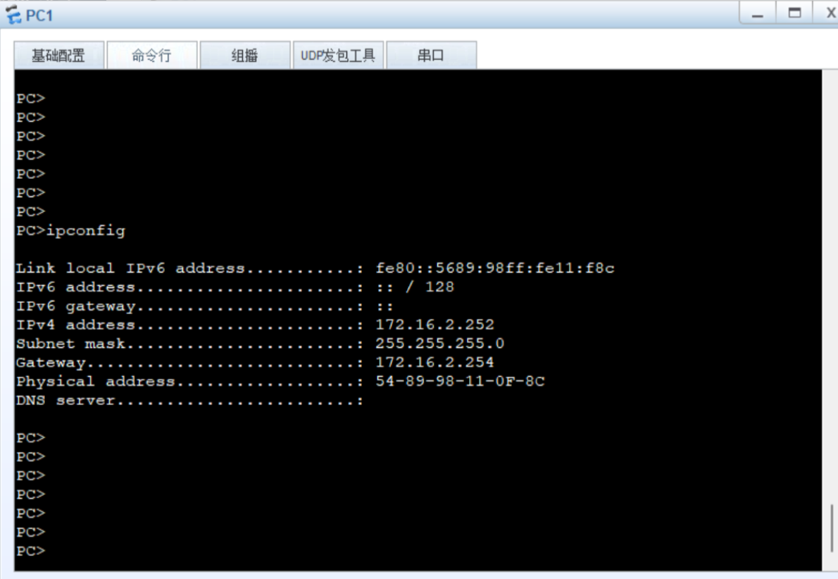
具体要求如图:
拓扑包含:
出口路由器:AR1
公网路由器:ISP
核心交换机:LSW1、LSW2
接入交换机:LSW3、LSW4
终端:PC1、PC2、PC3、PC4
需求:
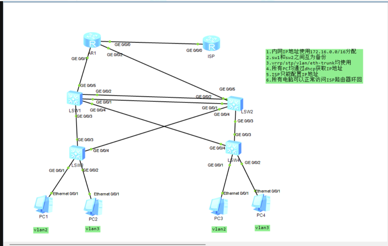
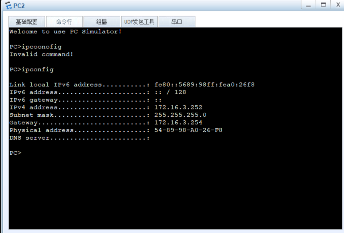
内网 IP:172.16.0.0/16(VLAN2:172.16.2.0/24,VLAN3:172.16.3.0/24);
核心交换机(LSW1/LSW2)互备,通过 Eth-Trunk、VRRP、MSTP 实现高可用;
所有 PC 通过 DHCP 自动获取 IP;
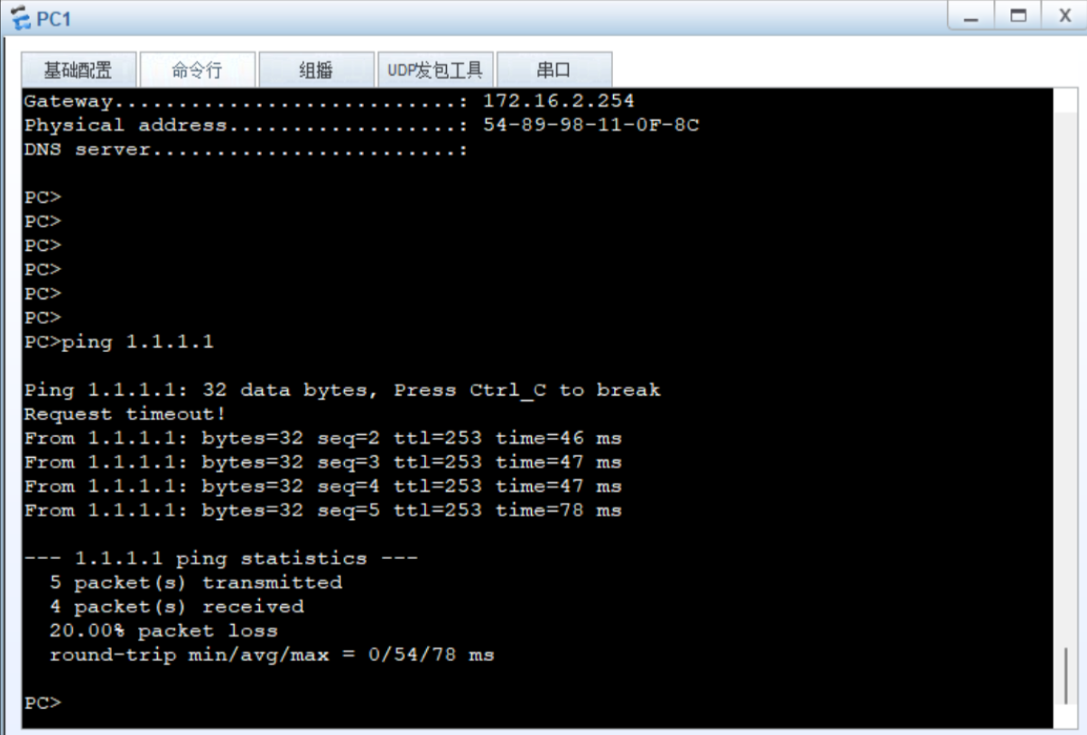
内网可访问 ISP 环回口(1.1.1.1)。
二、设备详细配置
1. 接入交换机 LSW3 配置
sysname LSW3
# VLAN创建与接口绑定
vlan batch 2 3
interface Ethernet0/0/1
port link-type access
port default vlan 2
interface Ethernet0/0/2
port link-type access
port default vlan 3
# 与核心交换机互联的Trunk链路
interface GigabitEthernet0/0/3
port link-type trunk
port trunk allow-pass vlan 2 3
2. 接入交换机 LSW4 配置
sysname LSW4
# VLAN创建与接口绑定
vlan batch 2 3
interface Ethernet0/0/1
port link-type access
port default vlan 2
interface Ethernet0/0/2
port link-type access
port default vlan 3
# 与核心交换机互联的Trunk链路
interface GigabitEthernet0/0/3
port link-type trunk
port trunk allow-pass vlan 2 3
3. 核心交换机 LSW1 配置
sysname LSW1
# VLAN创建
vlan batch 2 3 10 20
# Eth-Trunk冗余链路(与LSW2互联)
interface Eth-Trunk 1
port link-type trunk
port trunk allow-pass vlan 2 3 10 20
interface GigabitEthernet0/0/1
eth-trunk 1
interface GigabitEthernet0/0/2
eth-trunk 1
# 与AR1互联的VLANIF(IP:172.16.0.1/30)
interface Vlanif 10
ip address 172.16.0.1 255.255.255.252
dhcp select relay
dhcp relay server-ip 172.16.0.2 # AR1的G0/0/5接口IP
# VLAN2的VRRP与DHCP中继(主用)
interface Vlanif 2
ip address 172.16.2.1 255.255.255.0
vrrp vrid 2 virtual-ip 172.16.2.254
vrrp vrid 2 priority 110
dhcp select relay
dhcp relay server-ip 172.16.0.2
# VLAN3的VRRP与DHCP中继(备用)
interface Vlanif 3
ip address 172.16.3.1 255.255.255.0
vrrp vrid 3 virtual-ip 172.16.3.254
dhcp select relay
dhcp relay server-ip 172.16.0.2
# 与接入层互联的Trunk链路
interface GigabitEthernet0/0/3
port link-type trunk
port trunk allow-pass vlan 2 3
# MSTP配置(实例1对应VLAN2,实例2对应VLAN3)
stp region-configuration
region-name Huawei_MSTP
revision-level 1
instance 1 vlan 2
instance 2 vlan 3
active region-configuration
stp instance 1 root primary
stp instance 2 root secondary
4. 核心交换机 LSW2 配置
sysname LSW2
# VLAN创建
vlan batch 2 3 10 20
# Eth-Trunk冗余链路(与LSW1互联)
interface Eth-Trunk 1
port link-type trunk
port trunk allow-pass vlan 2 3 10 20
interface GigabitEthernet0/0/1
eth-trunk 1
interface GigabitEthernet0/0/2
eth-trunk 1
# 与AR1互联的VLANIF(IP:172.16.0.5/30)
interface Vlanif 20
ip address 172.16.0.5 255.255.255.252
dhcp select relay
dhcp relay server-ip 172.16.0.6 # AR1的G0/0/2接口IP
# VLAN2的VRRP与DHCP中继(备用)
interface Vlanif 2
ip address 172.16.2.2 255.255.255.0
vrrp vrid 2 virtual-ip 172.16.2.254
dhcp select relay
dhcp relay server-ip 172.16.0.6
# VLAN3的VRRP与DHCP中继(主用)
interface Vlanif 3
ip address 172.16.3.2 255.255.255.0
vrrp vrid 3 virtual-ip 172.16.3.254
vrrp vrid 3 priority 110
dhcp select relay
dhcp relay server-ip 172.16.0.6
# 与接入层互联的Trunk链路
interface GigabitEthernet0/0/3
port link-type trunk
port trunk allow-pass vlan 2 3
# MSTP配置(与LSW1完全一致,实例2为主根)
stp region-configuration
region-name Huawei_MSTP
revision-level 1
instance 1 vlan 2
instance 2 vlan 3
active region-configuration
stp instance 1 root secondary
stp instance 2 root primary
5. 出口路由器 AR1 配置
sysname AR1
# 接口IP配置
interface GigabitEthernet0/0/0
ip address 12.0.0.1 255.255.255.0
interface GigabitEthernet0/0/5
ip address 172.16.0.2 255.255.255.252
interface GigabitEthernet0/0/2
ip address 172.16.0.6 255.255.255.252
# DHCP地址池配置(VLAN2)
ip pool VLAN2
gateway-list 172.16.2.254
network 172.16.2.0 mask 255.255.255.0
# DHCP地址池配置(VLAN3)
ip pool VLAN3
gateway-list 172.16.3.254
network 172.16.3.0 mask 255.255.255.0
# OSPF动态路由(宣告所有直连与内网网段)
ospf 1
area 0
network 12.0.0.0 0.0.0.255
network 172.16.0.0 0.0.0.3
network 172.16.0.4 0.0.0.3
network 172.16.2.0 0.0.0.255
network 172.16.3.0 0.0.0.255
# NAT公网转换(ACL匹配内网网段)
acl 2000
rule permit source 172.16.2.0 0.0.0.255
rule permit source 172.16.3.0 0.0.0.255
interface GigabitEthernet0/0/0
nat outbound 2000
6. 公网路由器 ISP 配置
sysname ISP
# 接口与环回口IP配置
interface GigabitEthernet0/0/0
ip address 12.0.0.2 255.255.255.0
interface LoopBack0
ip address 1.1.1.1 255.255.255.0
# OSPF宣告公网与环回网段
ospf 1
area 0
network 12.0.0.0 0.0.0.255
network 1.1.1.0 0.0.0.255
三、实验验证步骤
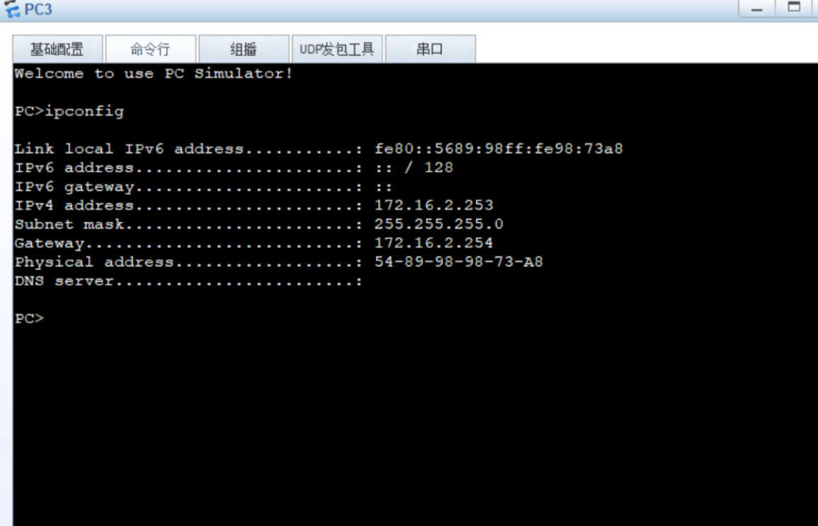
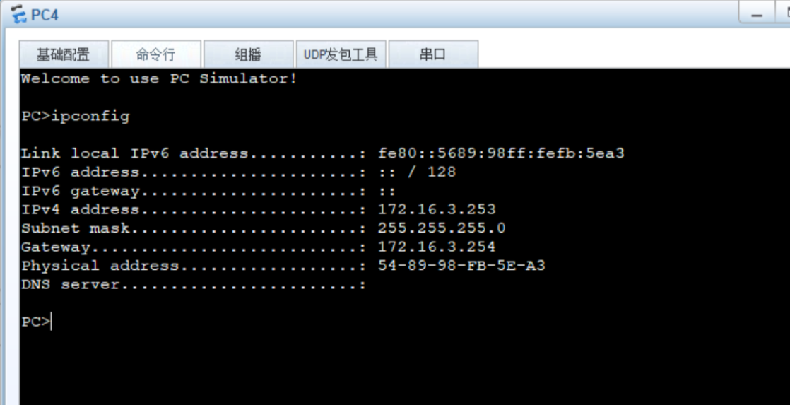
PC IP 获取验证:在 PC1-PC4 上执行ipconfig,应自动获取172.16.2.x或172.16.3.x地址,网关为172.16.2.254或172.16.3.254。
2.公网访问验证:在任意 PC 上执行ping 1.1.1.1,应能正常通信,说明 NAT 与 OSPF 配置生效。