STM32 异常和中断
异常与中断
1. 异常概述
文档说明
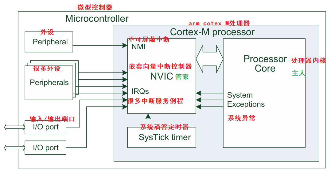
异常是指导致程序流程改变的事件。当异常发生时,处理器会暂停当前执行的任务,转而执行程序中称为异常处理程序的部分。完成异常处理程序的执行后,处理器即恢复正常程序执行。在ARM架构中,中断是异常的一种类型。中断通常由外设或外部输入产生,在某些情况下也可通过软件触发。针对中断的异常处理程序又被称为中断服务例程(ISR)。
每个异常源都有对应的异常编号。异常编号1至15属于系统异常,而编号16及以上的异常则用于中断。Cortex-M3和Cortex-M4处理器中的NVIC(嵌套向量中断控制器)设计最多可支持240个中断输入。然而实际设计中实现的中断输入数量要少得多,通常在16至100个之间。这种设计方式能缩小芯片面积,同时降低功耗。
NVIC 是 Cortex-M 处理器的一个组成部分,具有可编程特性,其寄存器位于内存映射的系统控制空间(SCS)。NVIC 负责异常和中断的配置、优先级管理以及中断屏蔽,主要功能包括:
- 灵活的异常与中断管理
- 支持异常/中断嵌套
- 向量化异常/中断入口
- 中断屏蔽功能
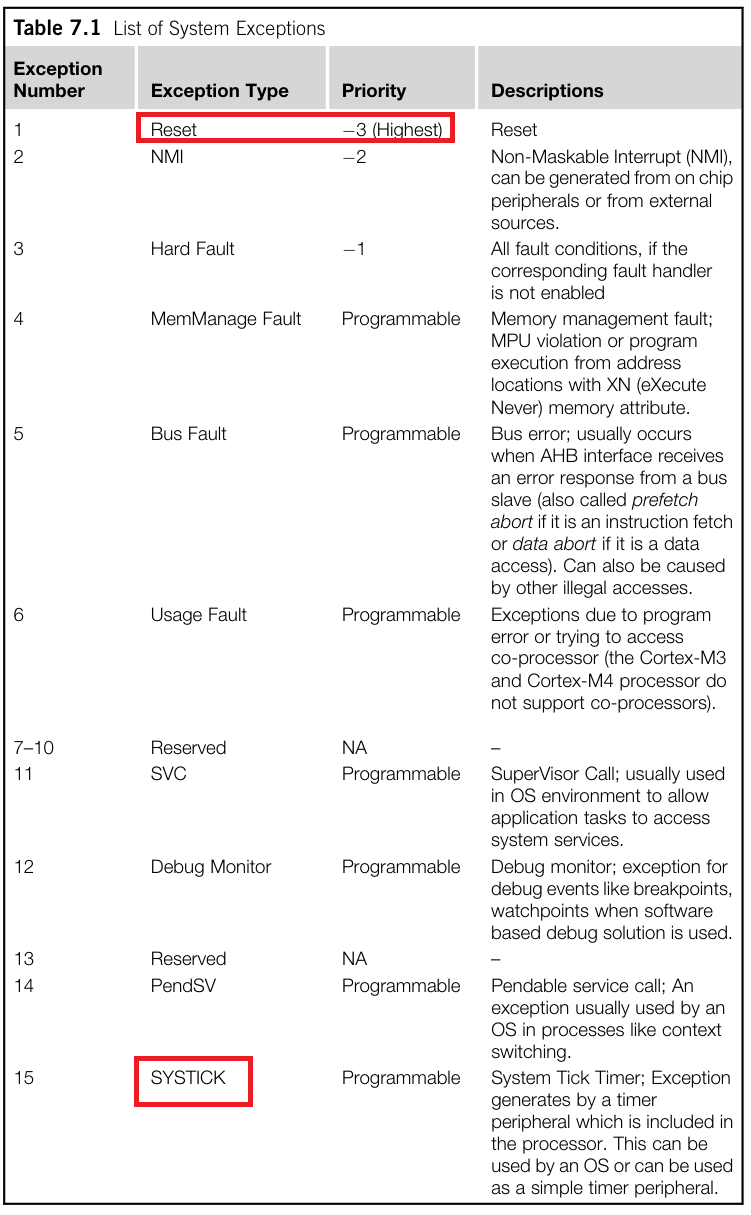
系统异常表
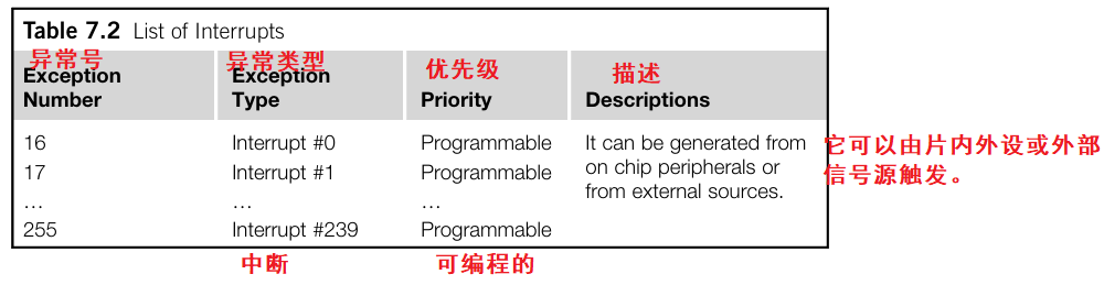
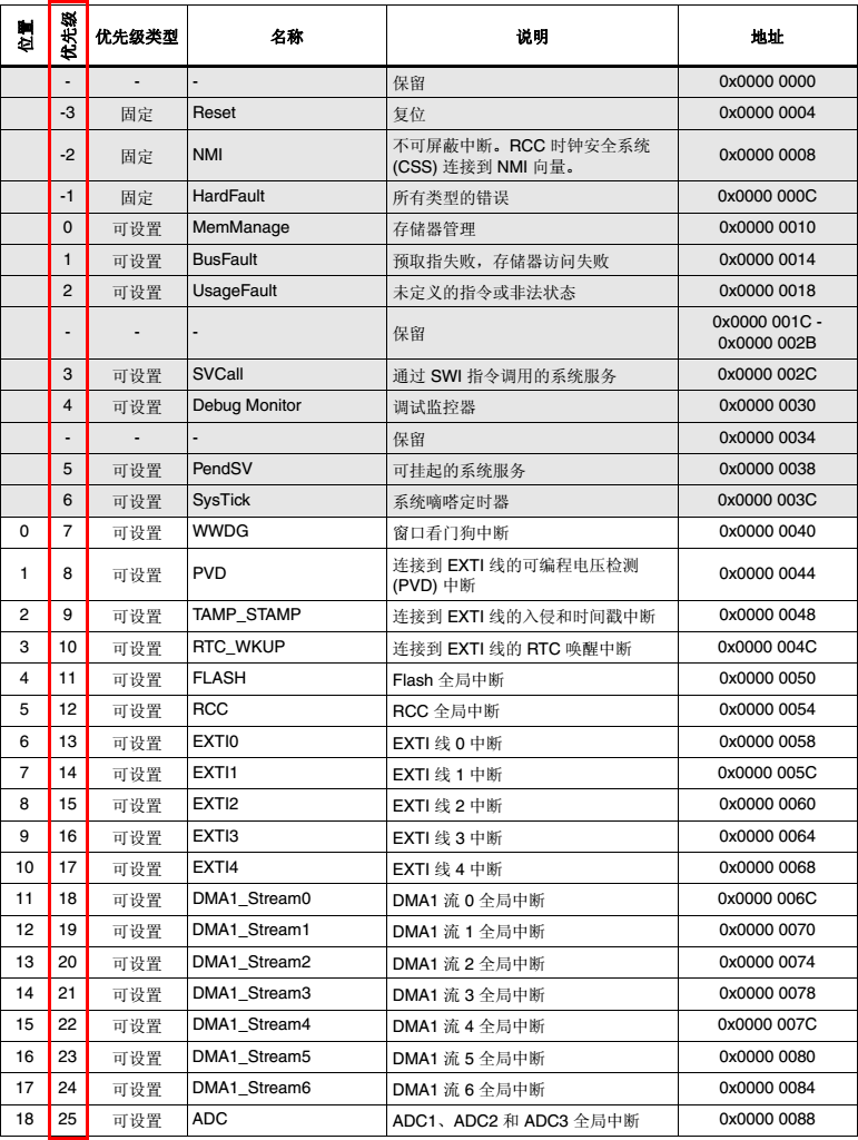
系统中断表
2. 中断线 注意事项
一、EXTI中断线的原理
STM32 的外部中断(EXTI)不是“每个引脚独立一个中断”,
而是按照“EXTI线号(Line)”来划分的:
| EXTI线号 | 可映射的引脚 |
|---|---|
| EXTI0 | PA0 / PB0 / PC0 / PD0 … |
| EXTI1 | PA1 / PB1 / PC1 / PD1 … |
| EXTI2 | PA2 / PB2 / PC2 / PD2 … |
| … | … |
也就是说:
- EXTI0 对应所有的
x0引脚(A0、B0、C0…) - EXTI1 对应所有的
x1引脚(A1、B1、C1…)
二、关键规则
一个 EXTI 线在同一时刻只能连接一个引脚。
例如:
- 如果你配置了 PA0 → EXTI0,
那么 PB0、PC0 等其他 0 号引脚就不能再用 EXTI0。 - 但你仍然可以使用 PA1 → EXTI1,互不干扰。
结论:
使用了 PA0(EXTI0)并不会影响 PA1(EXTI1)使用外部中断。
三、总结
STM32 里外部中断线(EXTI)只有 16 条(EXTI0–EXTI15),而不是每个 GPIO 各有一条。
这些中断线被所有端口的“同编号引脚”共用。
也就是说:
| EXTI线号 | 可选引脚 | 只能选其中一个! |
|---|---|---|
| EXTI0 | PA0 / PB0 / PC0 / PD0 / PE0 / PF0 / PG0 / PH0 / PI0 | 只能选一个 |
| EXTI1 | PA1 / PB1 / PC1 / PD1 / PE1 / PF1 / … | 只能选一个 |
| EXTI2 | PA2 / PB2 / PC2 / … | 只能选一个 |
| … | … | … |
| EXTI15 | PA15 / PB15 / PC15 / … | 只能选一个 |
中断服务配置
ST官方库中断模板示例:
- 初始化LED灯
用于在中断服务函数中点亮或闪烁 LED。 - EXTILine0_Config()
把 PA0 配置成外部中断输入,触发方式为 上升沿。 - EXTILine13_15_Config()
把 PG15(或 PC13)配置成外部中断输入,触发方式为 下降沿。 - EXTI_GenerateSWInterrupt()
手动生成一个软件中断,相当于人为模拟一次外部信号触发。 - while(1)
主循环保持运行,让中断随时能响应。
1. 初始化配置
(1) LED 相关片内外设的GPIO配置
RCC_AHB1PeriphClockCmd(RCC_AHB1Periph_GPIOA, ENABLE); // 开启 GPIOA 时钟
GPIO_InitStructure.GPIO_Mode = GPIO_Mode_IN;     // 输入模式
GPIO_InitStructure.GPIO_PuPd = GPIO_PuPd_NOPULL; // 无上下拉
GPIO_InitStructure.GPIO_Pin = GPIO_Pin_0;        // 选择 PA0
GPIO_Init(GPIOA, &GPIO_InitStructure);           // 初始化 GPIOA
(2) SYSCFG 寄存器的配置
SYSCFG 寄存器结构体
typedef struct
{uint32_t EXTI_Line;               /*!< Specifies the EXTI lines to be enabled or disabled.This parameter can be any combination value of @ref EXTI_Lines */EXTIMode_TypeDef EXTI_Mode;       /*!< Specifies the mode for the EXTI lines.This parameter can be a value of @ref EXTIMode_TypeDef */EXTITrigger_TypeDef EXTI_Trigger; /*!< Specifies the trigger signal active edge for the EXTI lines.This parameter can be a value of @ref EXTITrigger_TypeDef */FunctionalState EXTI_LineCmd;     /*!< Specifies the new state of the selected EXTI lines.This parameter can be set either to ENABLE or DISABLE */
}EXTI_InitTypeDef;
| 成员名称 | 类型 | 作用 | 常用取值 |
|---|---|---|---|
| EXTI_Line | uint32_t | 指定要配置的外部中断线编号(EXTI0~EXTI22) | EXTI_Line0, EXTI_Line1, …, EXTI_Line15, EXTI_Line17(RTC警报)等 |
| EXTI_Mode | EXTIMode_TypeDef | 设置该 EXTI 线的工作模式:中断 or 事件 | EXTI_Mode_Interrupt / EXTI_Mode_Event |
| EXTI_Trigger | EXTITrigger_TypeDef | 设置中断触发的信号边沿 | EXTI_Trigger_Rising / EXTI_Trigger_Falling / EXTI_Trigger_Rising_Falling |
| EXTI_LineCmd | FunctionalState | 控制该 EXTI 线是否使能 | ENABLE / DISABLE |
a. 开启SYSCFG时钟
RCC_APB2PeriphClockCmd(RCC_APB2Periph_SYSCFG, ENABLE);
b. 配置SYSCFG结构体
EXTI_InitStructure.EXTI_Line 	= EXTI_Line0;
EXTI_InitStructure.EXTI_Mode 	= EXTI_Mode_Interrupt;
EXTI_InitStructure.EXTI_Trigger = EXTI_Trigger_Rising;
EXTI_InitStructure.EXTI_LineCmd = ENABLE;
c. 将配置信息写入寄存器
EXTI_Init(&EXTI_InitStructure);
(3) 配置ARM内中断服务
a. 中断控制器结构体
typedef struct
{uint8_t NVIC_IRQChannel;                    /*!< Specifies the IRQ channel to be enabled or disabled.This parameter can be an enumerator of @ref IRQn_Type enumeration (For the complete STM32 Devices IRQ Channelslist, please refer to stm32f4xx.h file) */uint8_t NVIC_IRQChannelPreemptionPriority;  /*!< Specifies the pre-emption priority for the IRQ channelspecified in NVIC_IRQChannel. This parameter can be a valuebetween 0 and 15 as described in the table @ref MISC_NVIC_Priority_TableA lower priority value indicates a higher priority */uint8_t NVIC_IRQChannelSubPriority;         /*!< Specifies the subpriority level for the IRQ channel specifiedin NVIC_IRQChannel. This parameter can be a valuebetween 0 and 15 as described in the table @ref MISC_NVIC_Priority_TableA lower priority value indicates a higher priority */FunctionalState NVIC_IRQChannelCmd;         /*!< Specifies whether the IRQ channel defined in NVIC_IRQChannelwill be enabled or disabled. This parameter can be set either to ENABLE or DISABLE */
} NVIC_InitTypeDef;
- uint8_t NVIC_IRQChannel;
中断通道号(选择哪个中断)
| 中断源 | 对应通道(IRQn) | 说明 |
|---|---|---|
| EXTI0 外部中断线0 | EXTI0_IRQn | 对应 PA0、PB0、PC0 等中断 |
| EXTI15~10 外部中断线10~15 | EXTI15_10_IRQn | 对应多个按键共享同一个中断入口 |
| TIM2 定时器中断 | TIM2_IRQn | 定时器2溢出中断 |
| USART1 中断 | USART1_IRQn | 串口1中断 |
-
NVIC_IRQChannelPreemptionPriority
-
抢占优先级(主优先级)
-
一般为 0~15(值越小,优先级越高)。
-
NVIC_IRQChannelSubPriority
- 子优先级(同级比较顺序)
- 当两个中断的 抢占优先级相同 时,系统会根据 子优先级 决定谁先执行。
-
FunctionalState NVIC_IRQChannelCmd
- 是否使能该中断
注意:每条线需要单独配置
b. 将配置写入寄存器
NVIC_Init(&NVIC_InitStructure);
c. 中断优先级分组
说明:多个中断同时触发,应该先响应哪个中断
理解:
- 抢占式优先级低的,优先级高,是能抢占低抢占优先级的
- 相同抢占式优先级的,但是不同响应式优先级是不能抢占的
- 相同抢占式优先级的,如果同时响应,那么会先响应响应优先级低的,后响应响应优先级高的
- 相同抢占式优先级,相同响应式优先级,同时发生,那么会按照硬件内部固定的优先级顺序执行
  *  The table below gives the allowed values of the pre-emption priority and subpriority according*  to the Priority Grouping configuration performed by NVIC_PriorityGroupConfig function*    ==========================================================================================================================*      NVIC_PriorityGroup   | NVIC_IRQChannelPreemptionPriority | NVIC_IRQChannelSubPriority  |       Description*    ==========================================================================================================================*     NVIC_PriorityGroup_0  |                0                  |            0-15             | 0 bits for pre-emption priority*                           |                                   |                             | 4 bits for subpriority*    --------------------------------------------------------------------------------------------------------------------------*     NVIC_PriorityGroup_1  |                0-1                |            0-7              | 1 bits for pre-emption priority*                           |                                   |                             | 3 bits for subpriority*    --------------------------------------------------------------------------------------------------------------------------    *     NVIC_PriorityGroup_2  |                0-3                |            0-3              | 2 bits for pre-emption priority*                           |                                   |                             | 2 bits for subpriority*    --------------------------------------------------------------------------------------------------------------------------    *     NVIC_PriorityGroup_3  |                0-7                |            0-1              | 3 bits for pre-emption priority*                           |                                   |                             | 1 bits for subpriority*    --------------------------------------------------------------------------------------------------------------------------    *     NVIC_PriorityGroup_4  |                0-15               |            0                | 4 bits for pre-emption priority*                           |                                   |                             | 0 bits for subpriority                       *    ==========================================================================================================================
/**  * @brief  Configures the priority grouping: pre-emption priority and subpriority.  * @param  NVIC_PriorityGroup: specifies the priority grouping bits length.   *   This parameter can be one of the following values:  *     @arg NVIC_PriorityGroup_0: 0 bits for pre-emption priority    // 不支持抢占优先级(没有)  *                                4 bits for subpriority             // 支持16级响应优先级(0000-1111)响应优先级*     @arg NVIC_PriorityGroup_1: 1 bits for pre-emption priority    // 支持2级抢占优先级(0-1)  *                                3 bits for subpriority             // 支持8级响应优先级(000-111)先级*     @arg NVIC_PriorityGroup_2: 2 bits for pre-emption priority    // 支持4级抢占优先级(00-11)  *                                2 bits for subpriority             // 支持4级响应优先级(00-11)先级*     @arg NVIC_PriorityGroup_3: 3 bits for pre-emption priority    // 支持8级抢占优先级(000-111)  *                                1 bits for subpriority             // 支持2级响应优先级(0-1)先级*     @arg NVIC_PriorityGroup_4: 4 bits for pre-emption priority    // 支持16级抢占优先级(0000-1111)  *                                0 bits for subpriority             // 不支持响应优先级(没有)先级* @note   When the NVIC_PriorityGroup_0 is selected, IRQ pre-emption is no more possible.   *         The pending IRQ priority will be managed only by the subpriority.   * @retval None  */void NVIC_PriorityGroupConfig(uint32_t NVIC_PriorityGroup)roup)
注意:
- 只要开机初始化一次就可以了,一般我们将其放在main.c初始化的开头
- 我们一般设置为第二组,方便使用。默认也是第二组
注:以上均是学习笔记。