HCLP--ospf综合实验
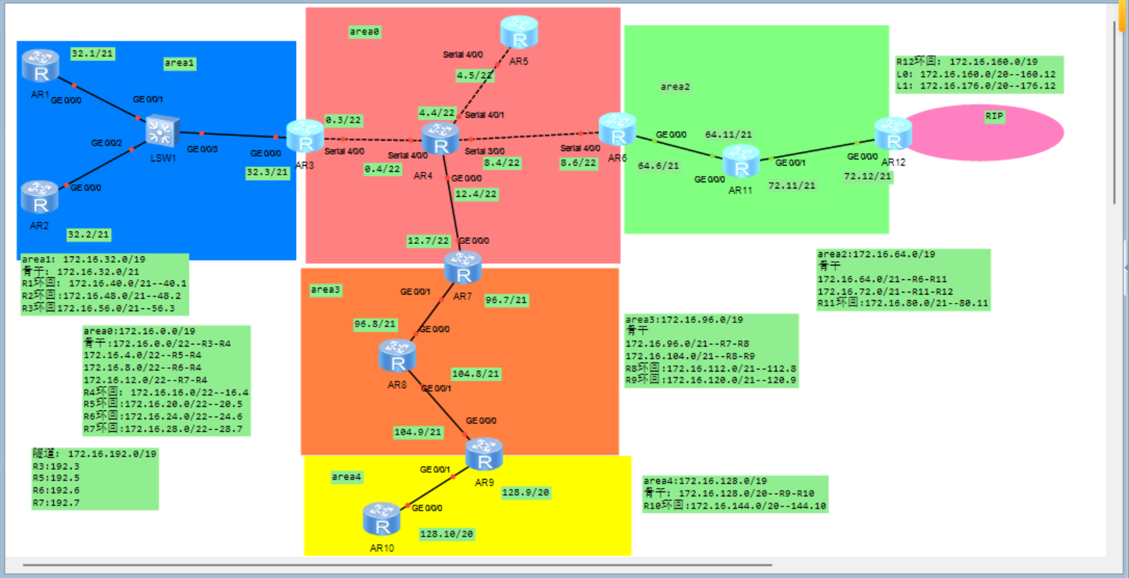
一、实验拓扑
二、实验需求
1、R4为ISP,其上只配置IP地址;R4与其他所直连设备间均使用公有IP;
2、R3-R5、R6、R7为MGRE环境,R3为中心站点;
3、整个OSPF环境IP基于172.16.0.0/16划分;除了R12有两个环回,其他路由器均有一个环回IP
4、所有设备均可访问R4的环回;
5、减少LSA的更新量,加快收敛,保障更新安全;
6、全网可达;
三、实验思路
1、根据广播域数量划分子网,并配置IP地址。
子网划分:按照区域划分,再划分骨干网段和环回。
2、配置ospf,rot-id,划分区域,宣告网段。
3、在R3-R7上配置MGRE,area0区域网络通畅,R4做ISP,在R3、R5~R7上分别创建隧道接口,配置IP地址,修改网络类型,配置源地址,设置nhrp域,R5~R7上配置注册信息到中心站点R3上,配置ospf宣告私网和隧道网段,实现全网可达。
4、配置easyIP,先配置ACL抓出流量,再在接口下下发ACL配置nat,使得私网公网互通,所有设备可以访问R4环回。
5、路由汇总,减少LSA更新量;缩短hello和dead的间隔时间,做防环操作配置黑洞路由,加快收敛;做ospf认证,保障更新安全。
6、测试。
四、实验步骤
1、划分子网
按照区域划分
172.16.0.0/16
Area 0
172.16.0000 0000.0 ----172.16.0.0/19---255.255.224.0
骨干
172.16.0000 0000.0----172.16.0.0/22--R3-R4
172.16.0000 0100.0----172.16.4.0/22--R5-R4
172.16.0000 1000.0----172.16.8.0/22--R6-R4
172.16.0000 1100.0----172.16.12.0/22--R7-R4
环回
172.16.0001 0000.0----172.16.16.0/22--R4环回
172.16.0001 0100.0----172.16.20.0/22--R5环回
172.16.0001 1000.0----172.16.24.0/22--R6环回
172.16.0001 1100.0----172.16.28.0/22--R7环回
Area1
172.16.0010 0000.0 ----172.16.32.0/19
骨干
172.16.0010 0000.0----172.16.32.0/21--R1、R2-R3
环回
172.16.0010 1000.0----172.16.40.0/21--R1环回
172.16.0011 0000.0----172.16.48.0/21--R2环回
172.16.0011 1000.0----172.16.56.0/21--R3环回
Area2
172.16.0100 0000.0 ----172.16.64.0/19
骨干
172.16.0100 0000.0---172.16.64.0/21--R6-R11
172.16.0100 1000.0----172.16.72.0/21--R11-R12
环回
172.16.0101 0000.0----172.16.80.0/21--R11环回
Area3
172.16.0110 0000.0 ----172.16.96.0/19
骨干
172.16.0110 0000.0----172.16.96.0/21--R7-R8
172.16.0110 1000.0----172.16.104.0/21--R8-R9
环回
172.16.0111 0000.0----172.16.112.0/21--R8环回
172.16.0111 1000.0----172.16.120.0/21--R9环回
Area4
172.16.1000 0000.0 ----172.16.128.0/19
172.16.1000 0000.0----172.16.128.0/20--R9-R10骨干
172.16.1001 0000.0----172.16.144.0/20--R10环回
RIP -- R12环回
172.16.1010 0000.0 ----172.16.160.0/19
172.16.1010 0000.0----172.16.160.0/20--R12环回L0
172.16.1011 0000.0----172.16.176.0/20--R12环回L1
隧道 (R3~R7MGRE)
172.16.1100 0000.0 ----172.16.192.0/19
2、配置IP地址
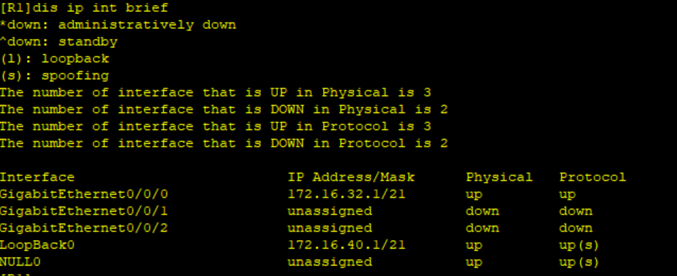
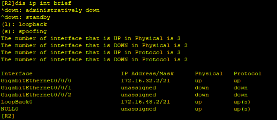
以R1为例
[R1]int g0/0/0
[R1-GigabitEthernet0/0/0]ip add 172.16.32.1 21
[R1-GigabitEthernet0/0/0]int l0
[R1-LoopBack0]ip add 172.16.40.1 21
[R1-LoopBack0]q
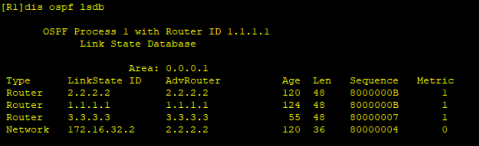
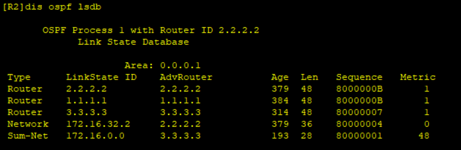
配置结果:
2、配置ospf协议
以R1为例,环回宣告到配置网段相应的区域。
[R1]ospf 1 router-id 1.1.1.1
[R1-ospf-1]a 1
[R1-ospf-1-area-0.0.0.1]net 172.16.32.0 0.0.7.255
[R1-ospf-1-area-0.0.0.1]net 172.16.40.1 0.0.0.0
[R1-ospf-1-area-0.0.0.1]q
[R1-ospf-1]q
配置结果:
area0:
area1:
area2:
R12环回(172.16.176.0网段配置到RIP中,将RIP引入到ospf协议中)
RIP配置:
[R12]rip 1
[R12-rip-1]v 2
[R12-rip-1]undo summary
[R12-rip-1]net 172.16.0.0
[R12-rip-1]q
引入ospf
[R12-ospf-1]import-route rip 1 type 1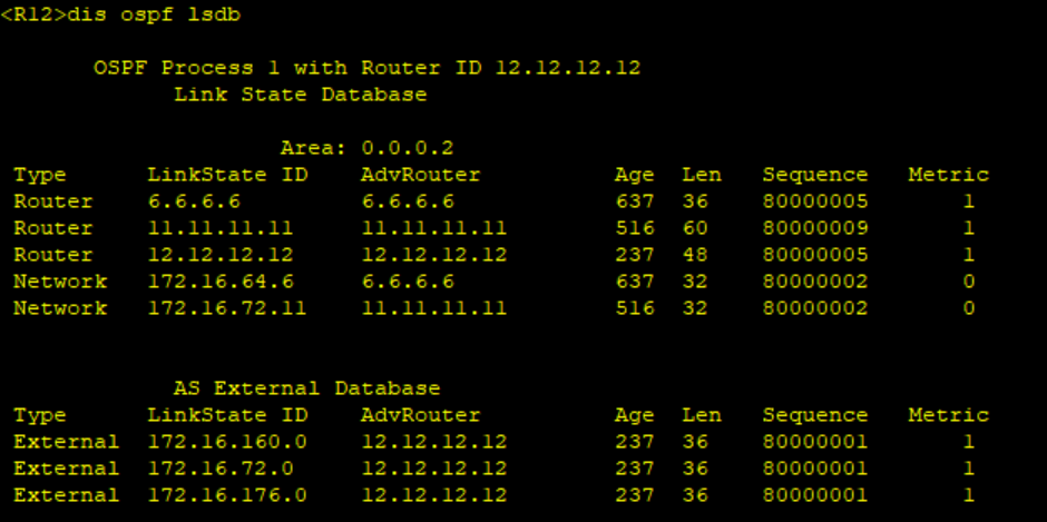
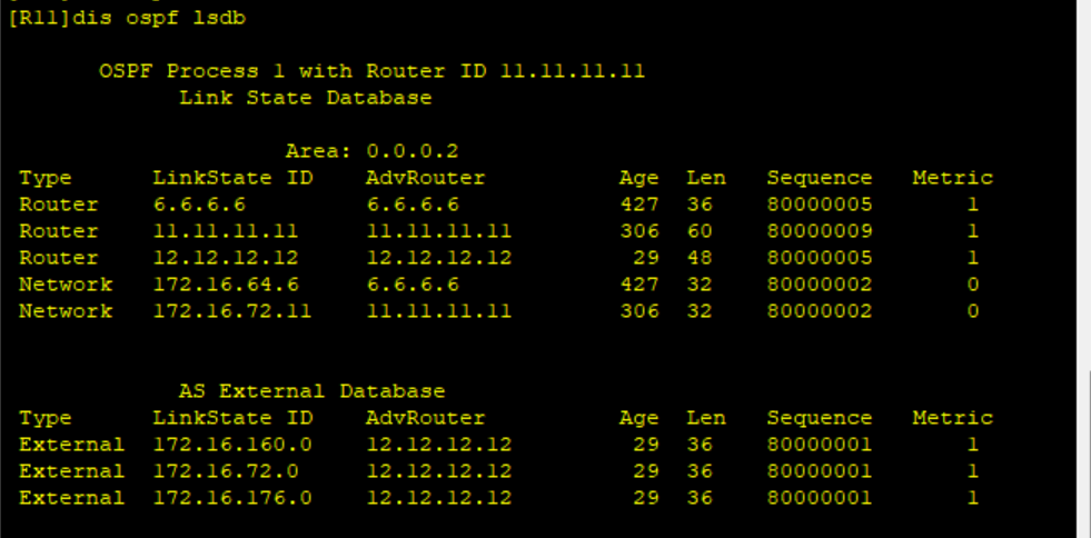
area3:
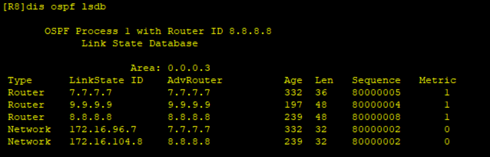
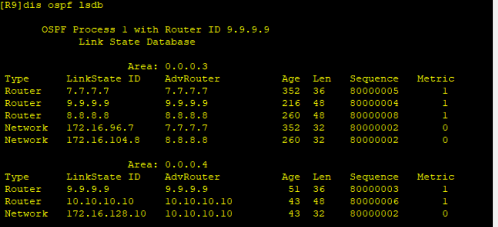
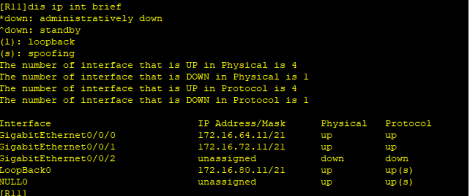
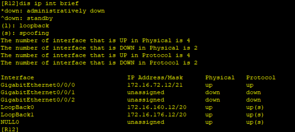
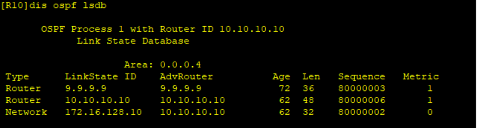
area4:
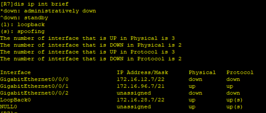
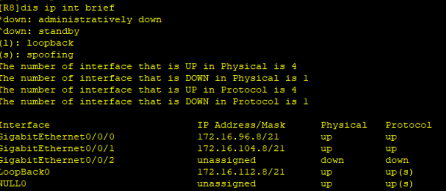
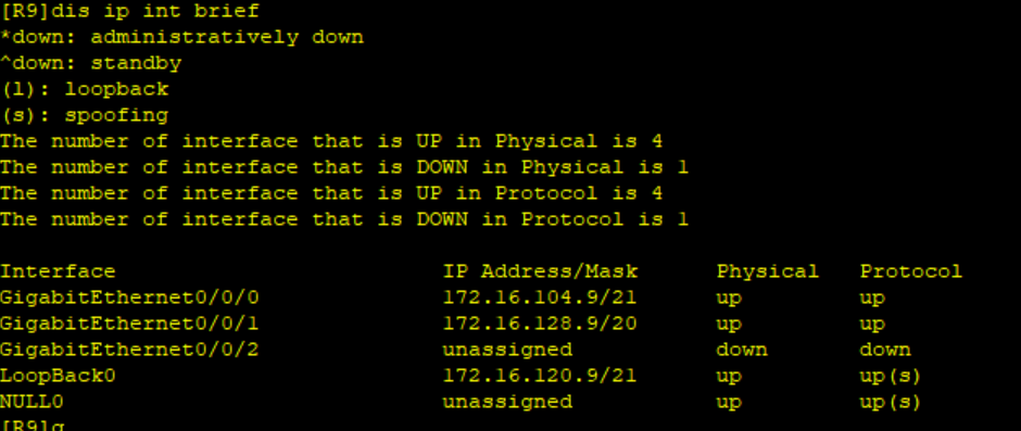
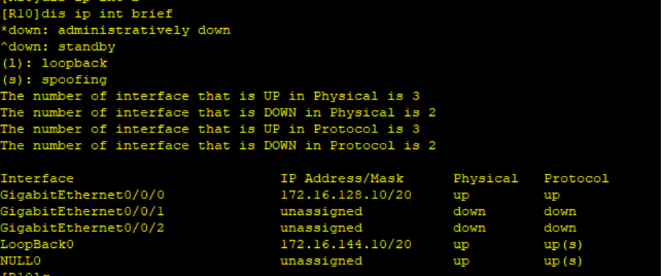
R10:
3、配置MGER
确保area0网络通常
也可以配置静态缺省
[R3]ip route-static 0.0.0.0 0 172.16.0.4
[R5]ip route-static 0.0.0.0 0 172.16.4.4
[R6]ip route-static 0.0.0.0 0 172.16.8.4
[R7]ip route-static 0.0.0.0 0 172.16.12.4
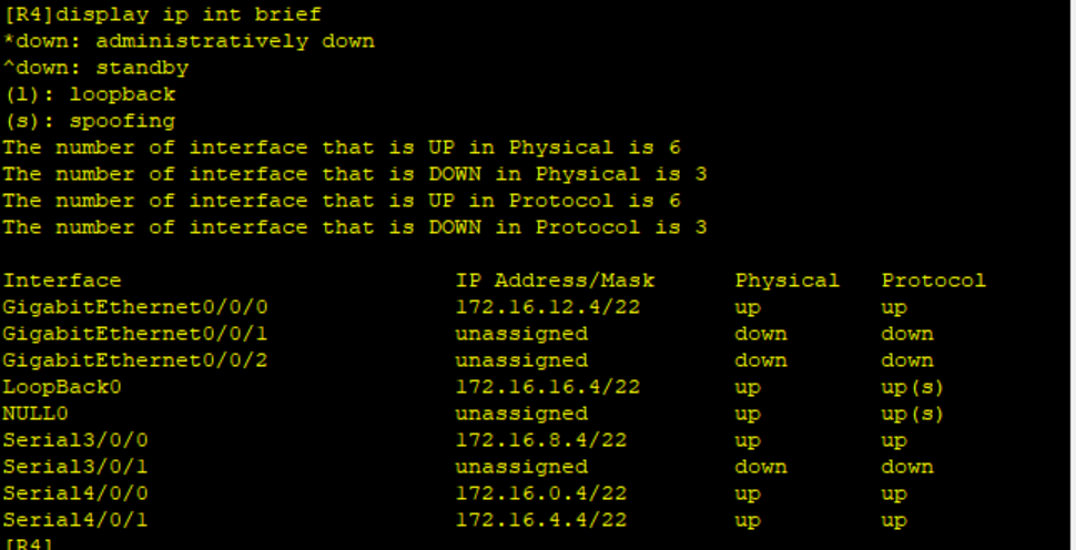
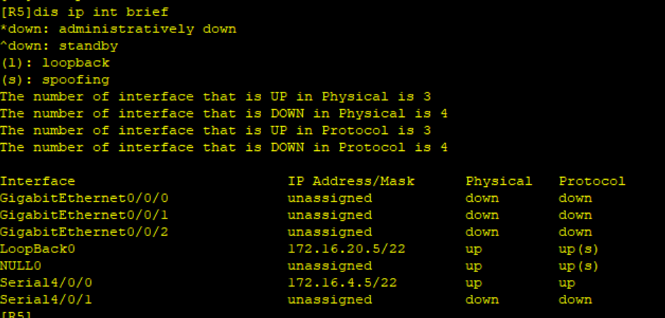
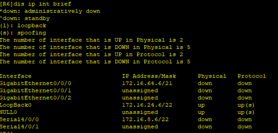
测试,R3ping通R5~R7:
创建隧道口,配置IP地址,定义封装方式,配置源地址,设置nhrp域,R5~R7注册信息到中心站点R3
R3:
[R3]int Tunnel 0/0/0
[R3-Tunnel0/0/0]ip add 172.16.192.3 19
[R3-Tunnel0/0/0]tunnel-protocol gre p2mp
[R3-Tunnel0/0/0]source 172.16.0.3
[R3-Tunnel0/0/0]nhrp network-id 100
[R3-Tunnel0/0/0]q
R5:
[R5]int Tunnel 0/0/0
[R5-Tunnel0/0/0]ip add 172.16.192.5 19
[R5-Tunnel0/0/0]tunnel-protocol gre p2mp
[R5-Tunnel0/0/0]source Serial 4/0/0
[R5-Tunnel0/0/0]nhrp network-id 100
[R5-Tunnel0/0/0]nhrp entry 172.16.0.3 172.16.192.3 register
[R5-Tunnel0/0/0]q
R6:
[R6]int Tunnel 0/0/0
[R6-Tunnel0/0/0]ip add 172.16.192.6 19
[R6-Tunnel0/0/0]tunnel-protocol gre p2mp
[R6-Tunnel0/0/0]source Serial 4/0/0
[R6-Tunnel0/0/0]nhrp network-id 100
[R6-Tunnel0/0/0]nhrp entry 172.16.0.3 172.16.192.3 register
[R6-Tunnel0/0/0]
[R6-Tunnel0/0/0]q
R7:
[R7]int Tunnel 0/0/0
[R7-Tunnel0/0/0]ip add 172.16.192.7 19
[R7-Tunnel0/0/0]tunnel-protocol gre p2mp
[R7-Tunnel0/0/0]source GigabitEthernet 0/0/0
[R7-Tunnel0/0/0]nhrp network-id 100
[R7-Tunnel0/0/0]nhrp entry 172.16.0.3 172.16.192.3 register
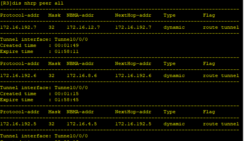
[R7-Tunnel0/0/0]在R3上查询配置结果:
配置ospf宣告私网和隧道网段,实现全网可达
需要再R4上配置ospf,或者配置静态路由
中心站点R3:
[R3]ospf 1 router-id 3.3.3.3
[R3-ospf-1]area 0
[R3-ospf-1-area-0.0.0.0]network 172.16.0.3 0.0.0.0
[R3-ospf-1-area-0.0.0.0]network 172.16.192.0 0.0.31.255
分支站点以R5为例:
[R5]ospf 1 router-id 5.5.5.5
[R5-ospf-1]a 0
[R5-ospf-1-area-0.0.0.0]network 172.16.4.5 0.0.0.0
[R5-ospf-1-area-0.0.0.0]network 172.16.20.5 0.0.0.0
[R5-ospf-1-area-0.0.0.0]network 172.16.192.0 0.0.31.255
配置结果:
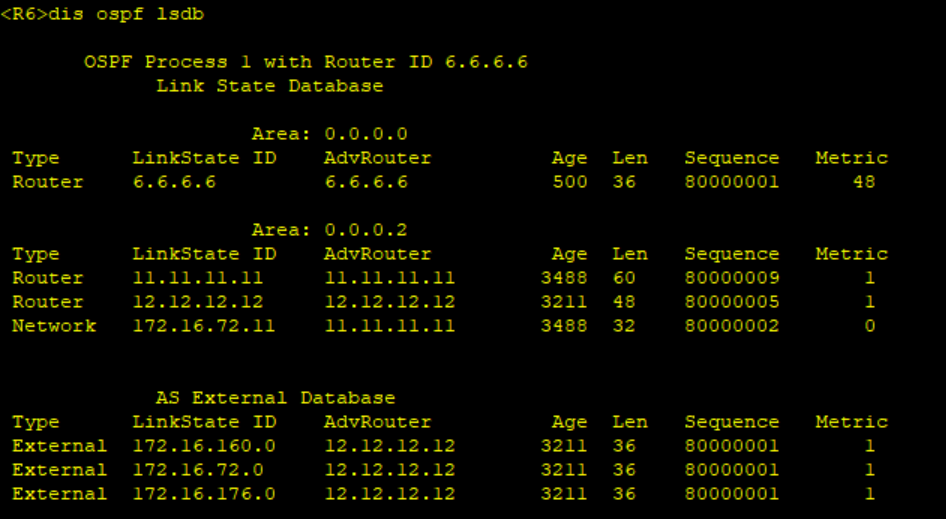
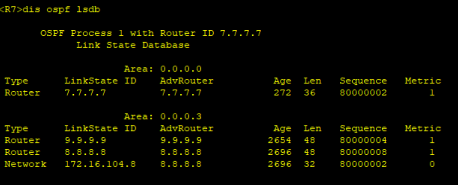
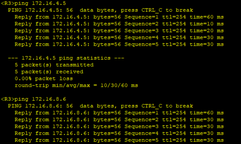
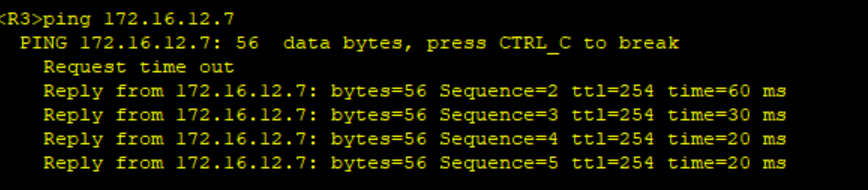
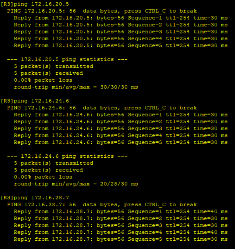
测试,R3可以访问R5~R7的环回:
 4、配置nat
配置ACL抓取流量
R3:
[R3]acl 2000
[R3-acl-basic-2000]rule permit source 172.16.32.0 0.0.31.255
[R3-acl-basic-2000]q
[R3]int Serial 4/0/0
[R3-Serial4/0/0]nat outbound 2000
[R3-Serial4/0/0]q
R5:
[R5]acl 2000
[R5-acl-basic-2000]rule permit source 172.16.20.0 0.0.3.255
[R5-acl-basic-2000]q
[R5]int Serial 4/0/0
[R5-Serial4/0/0]nat outbound 2000
[R5-Serial4/0/0]
R6:
[R6]acl 2000
[R6-acl-basic-2000]rule permit source 172.16.64.0 0.0.31.255
[R6-acl-basic-2000]q
[R6]int S4/0/0
[R6-Serial4/0/0]nat outbound 2000
[R6-Serial4/0/0]q
[R6]
R7:
[R7]acl 2000
[R7-acl-basic-2000]rule permit source 172.16.96.0 0.0.31.255
[R7-acl-basic-2000]rule permit source 172.16.128.0 0.0.31.255
[R7-acl-basic-2000]q
[R7]int g0/0/0
[R7-GigabitEthernet0/0/0]nat outbound 2000
[R7-GigabitEthernet0/0/0]q
[R7]
区域3与区域4之间
[R9]acl 2000
[R9-acl-basic-2000]rule permit source 172.16.128.0 0.0.31.255
[R9-acl-basic-2000]q
[R9]int g0/0/0
[R9-GigabitEthernet0/0/0]nat outbound 2000
[R9-GigabitEthernet0/0/0]q
[R9]
测试:
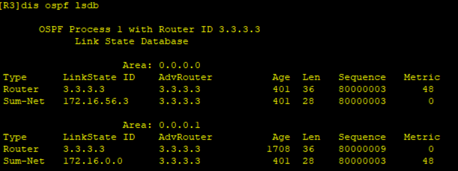
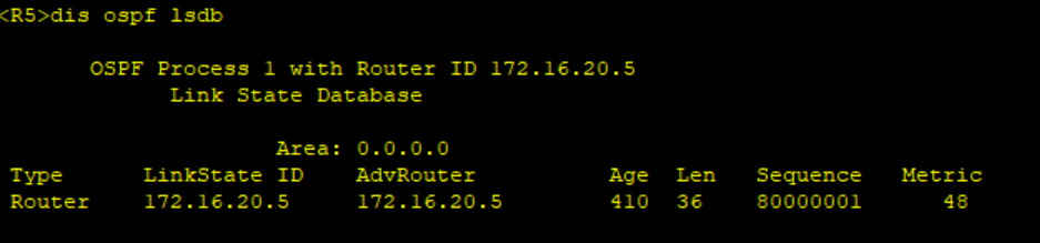
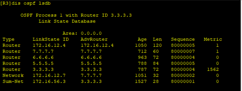
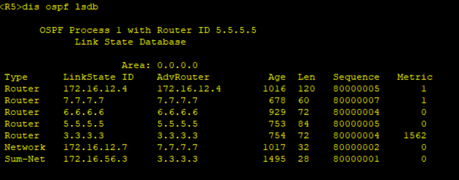
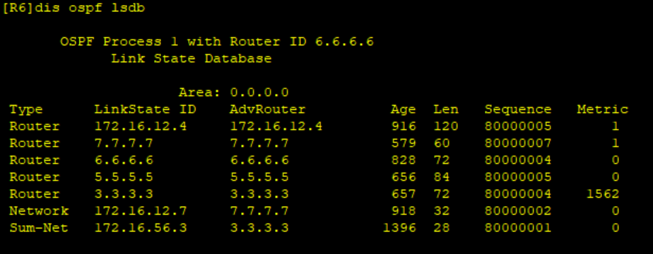
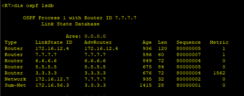
5、 减少LSA的更新量,加快收敛,保障更新安全
减少LSA的更新量,路由汇总,做防环操作,配置黑洞路由
[R3-ospf-1-area-0.0.0.1]network 172.16.0.0 0.0.255.255
[R6-ospf-1-area-0.0.0.0]net 172.16.0.0 0.0.255.255
[R7-ospf-1-area-0.0.0.0]net 172.16.0.0 0.0.255.255[R3]ip route-static 172.16.32.0 255.255.224.0 NULL 0
[R6]ip route-static 172.16.0.0 255.255.0.0 NULL 0
[R7]ip route-static 172.16.0.0 255.255.0.0 NULL 0
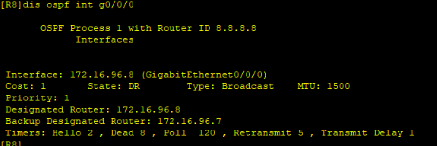
加快收敛,修改HELLO于死亡报文相隔时间
R7-R8:
[R7-GigabitEthernet0/0/1]ospf timer hello 2
[R8-GigabitEthernet0/0/0]ospf timer hello 2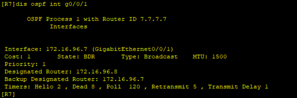
保障更新安全,配置ospf认证
R7-R8:
[R7-GigabitEthernet0/0/1]ospf authentication-mode md5 1 cipher xixi123
[R8-GigabitEthernet0/0/0]ospf authentication-mode md5 1 cipher xixi123
6、全网可达
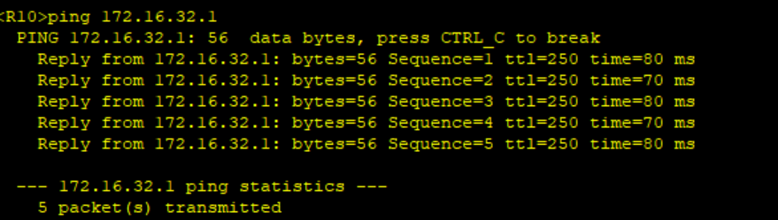
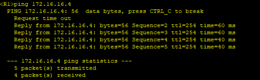
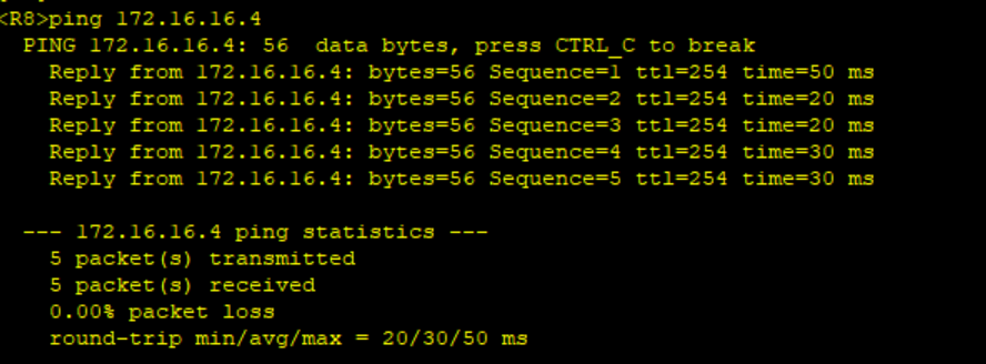
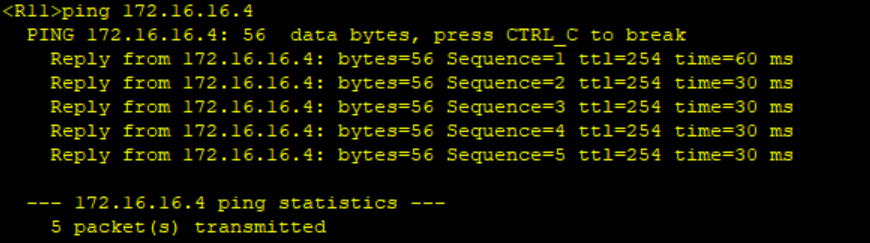
R1访问R12的环回
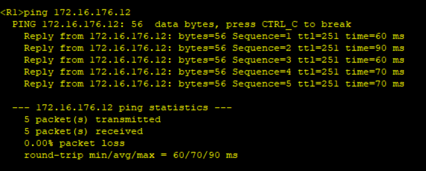
R10pingR1: