PT2000 Dev Studio产生的微码解析一-Channel 1
1、channel1微码
微码可以连接为写入PT2000 code RAM代码,这部分是NXP特殊定制的代码,格式内容参照PT2000SWUG.pdf文件(可到NXP官网下载)理解。
1.1、微码源码
注意:*符号后面的文字的为注释,不参与编译,可以或略。
********************************************************************************
* Example Code
*
* Copyright(C) 2025 NXP Semiconductors
* NXP Semiconductors Confidential and Proprietary
*
* Software that is described herein is for illustrative purposes only
* which provides customers with programming information regarding the
* NXP products.  This software is supplied "AS IS" without any warranties
* of any kind, and NXP Semiconductors and its licensor disclaim any and
* all warranties, express or implied, including all implied warranties of
* merchantability, fitness for a particular purpose and non-infringement of
* intellectual property rights.  NXP Semiconductors assumes no responsibility
* or liability for the use of the software, conveys no license or rights
* under any patent, copyright, mask work right, or any other intellectual
* property rights in or to any products. NXP Semiconductors reserves the
* right to make changes in the software without notification. NXP
* Semiconductors also makes no representation or warranty that such
* application will be suitable for the specified use without further testing
* or modification.
*
* IN NO EVENT WILL NXP SEMICONDUCTORS BE LIABLE, WHETHER IN CONTRACT,
* TORT, OR OTHERWISE, FOR ANY INCIDENTAL, SPECIAL, INDIRECT, CONSEQUENTIAL
* OR PUNITIVE DAMAGES, INCLUDING, BUT NOT LIMITED TO, DAMAGES FOR ANY
* LOSS OF USE, LOSS OF TIME, INCONVENIENCE, COMMERCIAL LOSS, OR LOST
* PROFITS, SAVINGS, OR REVENUES, TO THE FULL EXTENT SUCH MAY BE DISCLAIMED
* BY LAW. NXP SEMICONDUCTOR???S TOTAL LIABILITY FOR ALL COSTS, DAMAGES,
* CLAIMS, OR LOSSES WHATSOEVER ARISING OUT OF OR IN CONNECTION WITH THE
* SOFTWARE IS LIMITED TO THE AGGREGATE AMOUNT PAID BY YOU TO NXP SEMICONDUCTORS
* IN CONNECTION WITH THE SOFTWARE TO WHICH LOSSES OR DAMAGES ARE CLAIMED.
*
* Permission to use, copy, modify, and distribute this software and its
* documentation is hereby granted, under NXP Semiconductors' and its
* licensor's relevant copyrights in the software, without fee, provided
* that it is used in conjunction with NXP Semiconductors devices.  This
* copyright, permission, and disclaimer notice must appear in all copies
* of this code.
********************************************************************************* This microcore will control BANK1 #define HSBatB1   hs1;
#define HSBoostB1 hs2;
#define LS1B1     ls1;
#define LS2B1     ls2;#define HSBatB2   hs3;
#define HSBoostB2 hs4;
#define LS1B2     ls3;
#define LS2B2     ls4;*cur1 for ucore0
*cur2 for uCore1#include "dram1.def";* ### Initialization phase ###
init0:      stgn gain8.68 sssc;                     * Set the gain of the opamp of the current measure block 1ldjr1 eoinj0;                           * Load the eoinj line label Code RAM address into the register jr1 ldjr2 idle0;                            * Load the idle line label Code RAM address into the register jr2cwef jr1 _start row1;                   * If the start signal goes low, go to eoinj phase* ### Idle phase- the uPC loops here until start signal is present ###
idle0:      cwer CheckStart start row2;             * Define entry table for high start pinstoc on sssc;                           * Turn ON offset compensation
WaitLoop:   wait row2;                              * uPC is stuck here for almost the whole idle time
CheckStart: joslr inj1_start start1;                * Jump to inj1 if start 1 is highjoslr inj2_start start2;                * Jump to inj2 if start 2 is highjmpr WaitLoop;* ### Shortcuts definition per the injector to be actuated ###
inj1_start: dfsct HSBatB1 HSBoostB1 LS1B1;          * Set the 3 shortcuts: VBAT, VBOOST, LS2jmpr boost0;                            * Jump to launch phase
* ### Shortcuts definition per the injector to be actuated ###
inj2_start: dfsct HSBatB1 HSBoostB1 LS2B1;          * Set the 3 shortcuts: VBAT, VBOOST, LS2jmpr boost0;                            * Jump to launch phase* ### Launch phase enable boost ###
boost0:     stoc off sssc; load Iboost dac_sssc _ofs;              * Load the boost phase current threshold in the current DACcwer peak0 cur1 row2;                   * Jump to peak phase when current is over thresholdstf low b0;                             * set flag0 low to force the DC-DC converter in idle modestf high b1;                            * DEBUGstos on on on;                          * Turn VBAT off, BOOST on, LS onwait row12;                             * Wait for one of the previously defined conditions* ### Peak phase continue on Vbat ###
peak0:      ldcd rst _ofs keep keep Tpeak_tot c1;   * Load the length of the total peak phase in counter 1stos off off on;                        * Turn VBAT off, BOOST off, LS onload Ipeak dac_sssc _ofs;               * Load the peak current threshold in the current DACcwer bypass0 tc1 row2;                  * Jump to bypass phase when tc1 reaches end of countcwer peak_on0 tc2 row3;                 * Jump to peak_on when tc2 reaches end of countcwer peak_off0 cur1 row4;               * Jump to peak_off when current is over thresholdstf high b0;                            * set flag0 high to release the DC-DC converter idle mode
peak_init0: cwer peak_off0 _cur1 row5;              * Jump to peak_off when current is dischargedwait row125;peak_off0:  ldcd rst ofs keep keep Tpeak_off c2;    * Load in the counter 2 the length of the peak_off phasestos off off on;                        * Turn VBAT off, BOOST off, LS onwait row123;peak_on0:   stos on off on;                         * Turn VBAT on, BOOST off, LS onwait row124;                            * Wait for one of the previously defined conditions* ### Bypass phase ###
bypass0:    ldcd rst ofs keep keep Tbypass c3;      * Load in the counter 3 the length of the off_phase phasestos off off off;                       * Turn VBAT off, BOOST off, LS offcwer hold0 tc3 row4;                    * Jump to hold when tc3 reaches end of countwait row14;                             * Wait for one of the previously defined conditions* ### Hold phase on Vbat ###
hold0:      ldcd rst _ofs keep keep Thold_tot c1;   * Load the length of the total hold phase in counter 2load Ihold dac_sssc _ofs;               * Load the hold current threshold in the DACcwer eoinj0 tc1 row2;                   * Jump to eoinj phase when tc1 reaches end of countcwer hold_on0 tc2 row3;                 * Jump to hold_on when tc2 reaches end of countcwer hold_off0 ocur row4;               * Jump to hold_off when current is over thresholdhold_on0:   stos on off on;                         * Turn VBAT on, BOOST off, LS onwait row124;                            * Wait for one of the previously defined conditionshold_off0:  ldcd rst _ofs keep keep Thold_off c2;   * Load the length of the hold_off phase in counter 1stos off off on;                        * Turn VBAT off, BOOST off, LS onwait row123;* ### End of injection phase ###
eoinj0:     stos off off off;                       * Turn VBAT off, BOOST off, LS offstf high b0;                            * set flag0 to high to release the DC-DC converter idle modejmpf jr2;                               * Jump back to idle phase* ### End of Channel 1 - uCore0 code ###*###############################################################################################################################
* ### Initialization phase ###
init1:      stgn gain8.68 sssc;                     * Set the gain of the opamp of the current measure block 1ldjr1 eoinj1;                           * Load the eoinj line label Code RAM address into the register jr1ldjr2 idle1;                            * Load the idle line label Code RAM address into the register jr2cwef jr1 _start row1;                   * If the start signal goes low, go to eoinj phasebias all on;* ### Idle phase- the uPC loops here until start signal is present ###
idle1:      stoc on sssc;                           * Turn ON offset compensationcwer CheckStart1 start row2;            * Define entry table for high start pin
WaitLoop1:  wait row2;                              * uPC is stuck here for almost the whole idle time
CheckStart1:joslr inj3_start start3;                * Jump to inj3 if start 3 is highjoslr inj4_start start4;                * Jump to inj4 if start 4 is highjmpr WaitLoop1;* ### Shortcuts definition per the injector to be actuated ###
inj3_start: dfsct HSBatB2 HSBoostB2 LS1B2;          * Set the 3 shortcuts: VBAT, VBOOST, LS2jmpr boost1;                            * Jump to launch phase
* ### Shortcuts definition per the injector to be actuated ###
inj4_start: dfsct HSBatB2 HSBoostB2 LS2B2;          * Set the 3 shortcuts: VBAT, VBOOST, LS2jmpr boost1;                            * Jump to launch phase* ### Launch phase enable boost ###
boost1:     stoc off sssc;load Iboost dac_sssc _ofs;              * Load the boost phase current threshold in the current DACcwer peak1 cur2 row2;                   * Jump to peak phase when current is over thresholdstf low b0;                             * set flag0 low to force the DC-DC converter in idle modestf high b2;                            * DEBUGstos on on on;                          * Turn VBAT off, BOOST on, LS onwait row12;                             * Wait for one of the previously defined conditions* ### Peak phase continue on Vbat ###
peak1:      ldcd rst _ofs keep keep Tpeak_tot c1;   * Load the length of the total peak phase in counter 1stos off off on;                        * Turn VBAT off, BOOST off, LS onload Ipeak dac_sssc _ofs;               * Load the peak current threshold in the current DACcwer bypass1 tc1 row2;                  * Jump to bypass phase when tc1 reaches end of countcwer peak_on1 tc2 row3;                 * Jump to peak_on when tc2 reaches end of countcwer peak_off1 cur2 row4;               * Jump to peak_off when current is over thresholdstf high b0;                            * set flag0 high to release the DC-DC converter idle mode
peak_init1: cwer peak_off1 _cur2 row5;              * Jump to peak_off when current is dischargedwait row125;peak_off1:  ldcd rst ofs keep keep Tpeak_off c2;    * Load in the counter 2 the length of the peak_off phasestos off off on;                        * Turn VBAT off, BOOST off, LS onwait row123;peak_on1:   stos on off on;                         * Turn VBAT on, BOOST off, LS onwait row124;                            * Wait for one of the previously defined conditions* Wait for one of the previously defined conditions* ### Bypass phase ###
bypass1:    ldcd rst ofs keep keep Tbypass c3;      * Load in the counter 3 the length of the off_phase phasestos off off off;                       * Turn VBAT off, BOOST off, LS offcwer hold1 tc3 row4;                    * Jump to hold when tc3 reaches end of countwait row14;                             * Wait for one of the previously defined conditions* ### Hold phase on Vbat ###
hold1:      ldcd rst _ofs keep keep Thold_tot c1;   * Load the length of the total hold phase in counter 2load Ihold dac_sssc _ofs;               * Load the hold current threshold in the DACcwer eoinj1 tc1 row2;                   * Jump to eoinj phase when tc1 reaches end of countcwer hold_on1 tc2 row3;                 * Jump to hold_on when tc2 reaches end of countcwer hold_off1 cur2 row4;               * Jump to hold_off when current is over thresholdhold_on1:   stos on off on;                         * Turn VBAT on, BOOST off, LS onwait row124;                            * Wait for one of the previously defined conditionshold_off1:  ldcd rst _ofs keep keep Thold_off c2;   * Load the length of the hold_off phase in counter 1stos off off on;                        * Turn VBAT off, BOOST off, LS onwait row123;* ### End of injection phase ###
eoinj1:     stos off off off;                       * Turn VBAT off, BOOST off, LS offstf high b0;                            * set flag0 to high to release the DC-DC converter idle modejmpf jr2;                               * Jump back to idle phase* ### End of Channel 1 - uCore1 code ###
1.2、微码解析
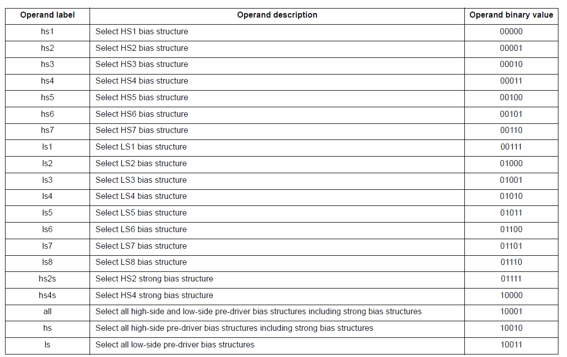
1)#define HSBatB1 hs1; #define HSBoostB1 hs2; #define LS1B1 ls1; #define LS2B1 ls2; #define HSBatB2 hs3; #define HSBoostB2 hs4; #define LS1B2 ls3; #define LS2B2 ls4;
定义hs1、hs2、ls1、ls2、hs3、hs4、ls3及ls4标签换成用户较熟悉的HSBatB1、HSBoostB1 、LS1B1 、LS2B1 、HSBatB2 、HSBoostB2 、LS1B2 及LS2B2 标签,这个标签在PT2000SWUG.pdf文件里有如下定义(实际值就是下表的第三列的二进制值):
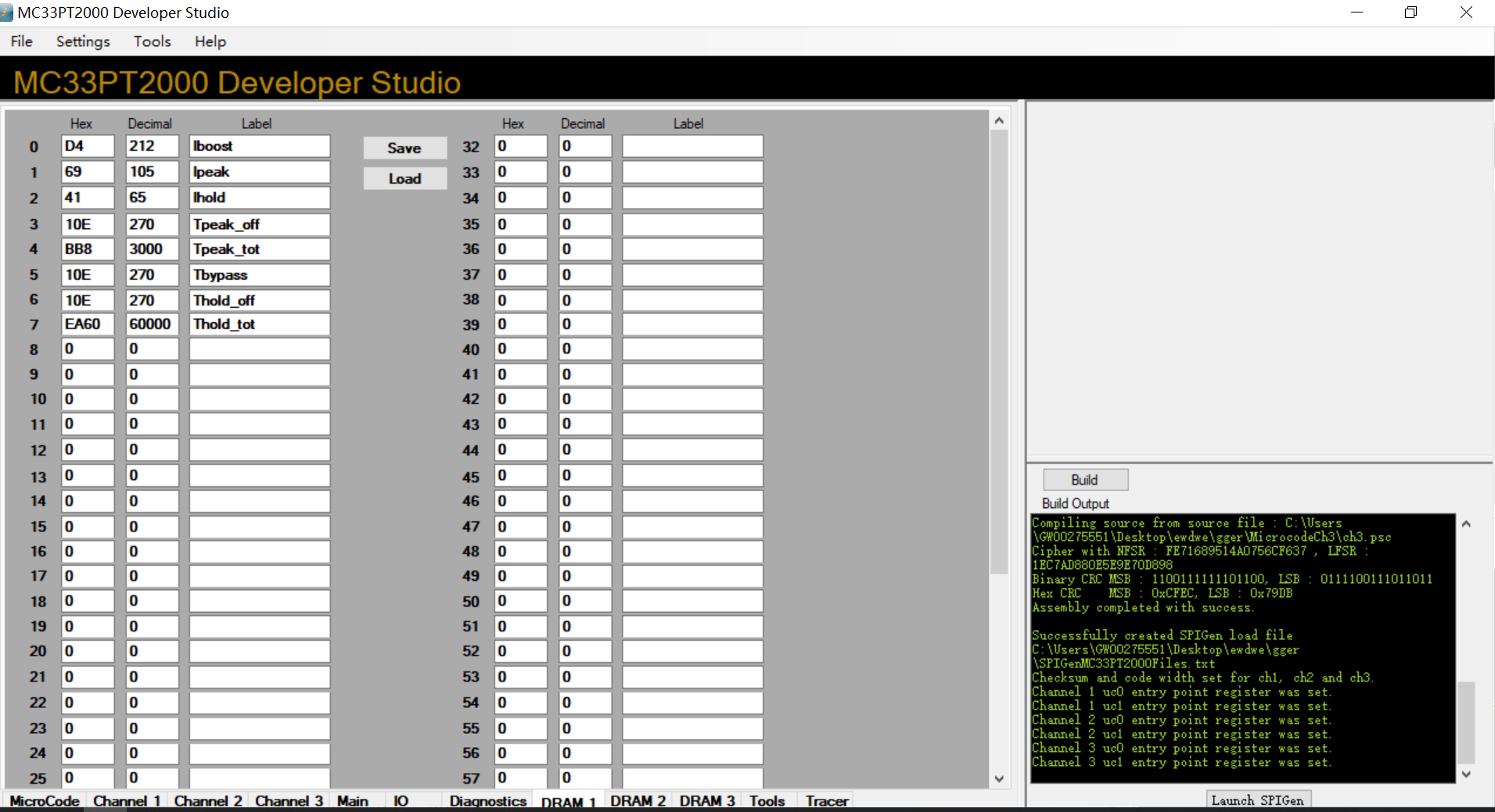
2)#include "dram1.def";
包含DRAM1的数据,也就是微码会引用下图中label列标签。引用这些label就是引用前面对应的HEX/Decimal值。
3)init0: stgn gain8.68 sssc;
init0:只是个行标签,表示在channel1 uc0初始化的含义,PT2000SWUG.pdf文件未说明,猜测就是类似于放在C语言中放在main()里while(1)之前的初始化部分。
stgn:Set current measure operational amplifier gain,设置电流测量增益,参数有如下几种(对应的值是第三列),和MC33PT2000手册上对应。
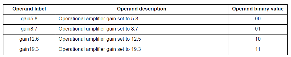
gain8.68:为啥不是上图的gain8.7,未理解,怀疑是PT2000SWUG.pdf文件错误
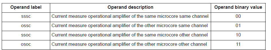
sssc:这个参数意思是在相同channel,相同microcore处理,具体指就是第三列的00b,在这里的意思就是说在channel1 uc0核处理。
4)ldjr1 eoinj0;
跳转到结束喷油的含义
ldjr1:Load jump register 1 跳转寄存器1
eoinj0:行标签,end of injection phase,结束喷油
5)ldjr2 idle0;
类似于4),跳转到标签idle0
6)