配电系统接地 | TT, TN-C, TNC-S,TN-S, IT
注:本文为 “配电系统接地” 相关合辑。
英文引文,机翻未校。
中文引文,略作重排,未全去重,存疑互校。
图片清晰度受引文原图所限。
如有内容异常,请看原文。
Erection of earthing arrangements (TNC, TN-S, TNC-S, TT)
接地装置(TNC、TN-S、TNC-S、TT 系统)的安装
Edvard Csanyi
Energy and Power / Protection / Safety / Testing and Commissioning
能源与电力 / 保护 / 安全 / 测试与调试
Erection of earthing arrangements (TNC, TN-S, TNC-S, TT)
接地装置(TNC、TN-S、TNC-S、TT 系统)的安装
Earthing of low voltage networks
低压电网接地
The earthing arrangements (TNC, TN-S, TNC-S, TT) of low voltage networks is largely determined by the Low Voltage Supplies. However, if the incoming supplies are at 11kV and the transformers are in the ownership of the user, the LV supplies may be earthed in a less conventional way using a high impedance. This arrangement is not allowed for public supplies.
低压电网的接地装置(TNC、TN-S、TNC-S、TT 系统)在很大程度上由低压电源决定。然而,若引入电源为 11kV 且变压器归用户所有,则低压电源可采用非传统的高阻抗接地方式。该接地方式不允许用于公共供电系统。
However, it is a useful system when it is more important to maintain supplies than it is to clear the first earth fault.
但在“维持供电”比“清除首次接地故障”更重要的场景中,该系统具有实用价值。
EXAMPLE: An emergency lighting scheme for the evacuation of personnel from a hazardous area could use a high impedance system if it were considered less dangerous to maintain supplies after a first earth fault than to disconnect the light completely. The Channel Tunnel could be such a case.
示例:在危险区域人员疏散用应急照明系统中,若认为“首次接地故障后维持供电”比“完全切断照明”的危险性更低,则可采用高阻抗接地系统。英吉利海峡隧道(Channel Tunnel)就可能属于此类情况。
Even in these circumstances the original earth fault should be corrected as quickly as possible.
即便在上述场景下,也应尽快排除初始接地故障。
The more conventional earthing arrangements are:
更为传统的接地装置包括:
- TN-C where the earth and neutral are combined (PEN) and
TN-C 系统:接地与中性线合并(即保护中性线 PEN); - TN-S where they are separated (5 wire) or
TN-S 系统:接地与中性线分离(即 5 线制); - TN-C-S.
TN-C-S 系统。
The latter is very common as it allows the single-phase loads to be supplied by phase and neutral with a completely separate earth system connecting together all the exposed conductive parts before connecting them to the PEN conductor via a main earthing terminal which is also connected to the neutral terminal.
其中,TN-C-S 系统应用十分广泛:该系统可通过相线和中性线为单相负载供电,同时具备完全独立的接地系统——所有外露导电部件先相互连接,再通过总接地端子(该端子同时与中性端子连接)接入 PEN 线。
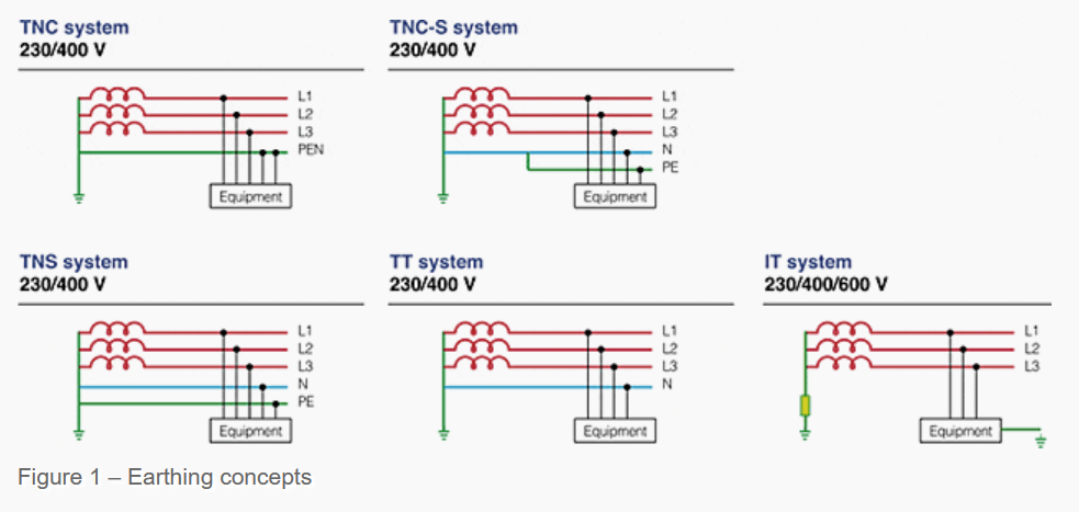
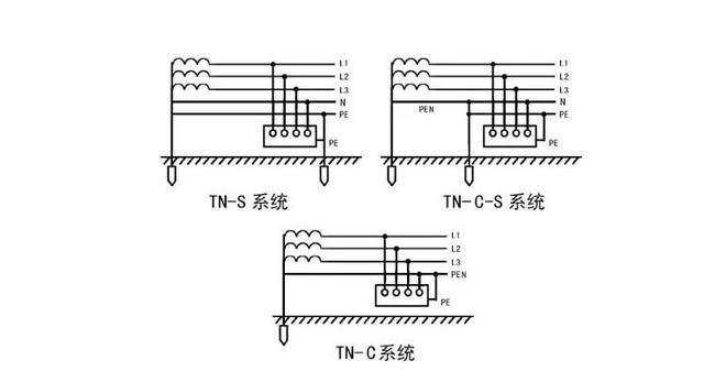
Figure 1 – Earthing concepts
图 1——接地概念
Earthing concepts
接地概念
Figure 1 – Earthing concepts
图 1——接地概念
For protective conductors of the same material as the phase conductor the cross-sectional area shall be the same size as the phase conductor up to 16mm216 \, \text{mm}^216mm2.
若保护导体与相线材质相同,则当相线截面积不超过 16mm216 \, \text{mm}^216mm2 时,保护导体的截面积应与相线一致。
IMPORTANT: When the phase conductor is above 16mm216 \, \text{mm}^216mm2 then the protective conductor may remain at 16mm216 \, \text{mm}^216mm2 until the phase conductor is 35mm235 \, \text{mm}^235mm2, after which the protective conductor should be half the size of the phase conductor.
重要提示:当相线截面积超过 16mm216 \, \text{mm}^216mm2 时,若相线截面积不超过 35mm235 \, \text{mm}^235mm2,保护导体截面积仍可保持为 16mm216 \, \text{mm}^216mm2;若相线截面积超过 35mm235 \, \text{mm}^235mm2,则保护导体截面积应取相线截面积的一半。
For conductors which are not of the same material the cross-sectional area shall be adjusted in the ratios of the factor kkk from Table 43A in BS 7671. The kkk factor takes into account the resistivity, temperature coefficient and heat capacity of the conductor materials and of the initial and final temperatures.
若保护导体与相线材质不同,则需根据 BS 7671 标准中表 43A 给出的系数 kkk 的比值调整保护导体的截面积。系数 kkk 综合考虑了导体材料的电阻率、温度系数、热容,以及导体的初始温度和最终温度。
TN-S system
TN-S 系统
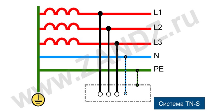
In a TN-S system (Figure 1), the Neutral and Protective conductors must remain distinct throughout the system, and the source is solidly grounded.
在 TN-S 系统(图 1)中,中性线(Neutral)与保护线(Protective)在整个系统中必须始终分离,且电源侧采用直接接地(solidly grounded)。
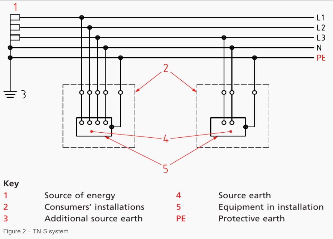
A TN-S system possesses a specific drawback: if the protective conductor becomes an open circuit, there is no notice of a failure, potentially leaving installations unknowingly without an earth connection. In the occurrence of an earth fault, all exposed conductive components within a consumer installation may attain a dangerous voltage.
TN-S 系统存在一个特定缺陷:若保护线发生开路,故障不会发出任何提示信号,可能导致设备在未察觉的情况下失去接地连接。一旦发生接地故障,用户设备内所有外露导电部件都可能带上危险电压。
Earth fault protection devices will remain inoperative due to the absence of current flow to the ground.
由于没有接地电流通路,接地故障保护装置将无法动作。
See Figure 2.
Figure 2 – TN-S system
图 2——TN-S 系统
TN-C system
TN-C 系统
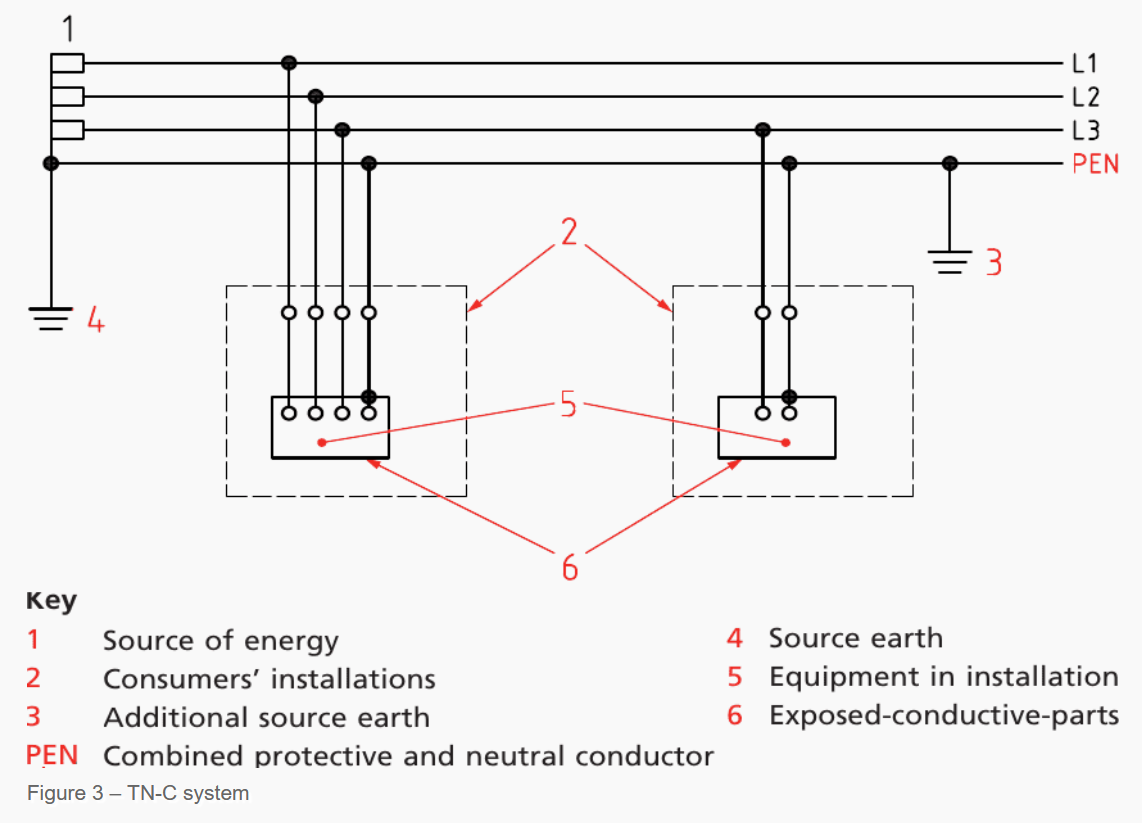
In a TN-C system (Figure 2), the neutral and protective functions must be integrated into a single conductor (PEN) throughout the entire system. It is advisable to have multiple connections to earth along the PEN conductor, with the source being securely earthed.
在 TN-C 系统(图 2)中,中性线功能与保护线功能在整个系统中必须集成到一根导体(即 PEN 线,保护中性线)中。建议沿 PEN 线设置多处接地连接,且电源侧需可靠接地。
The necessity for multiple earth connections arises from the potential for the neutral to become an open circuit. In such instances, exposed conductive parts may elevate to line-to-earth voltage in single-phase systems, and may reach values up to line-to-earth voltage in three-phase systems, contingent upon the extent of load unbalance.
设置多处接地的必要性源于中性线可能发生开路的风险:在单相系统中,若中性线开路,外露导电部件可能升至线对地电压;在三相系统中,外露导电部件的电压则可能根据负载不平衡程度升至线对地电压。
See Figure 3.
Figure 3 – TN-C system
图 3——TN-C 系统
TN-C-S system
TN-C-S 系统
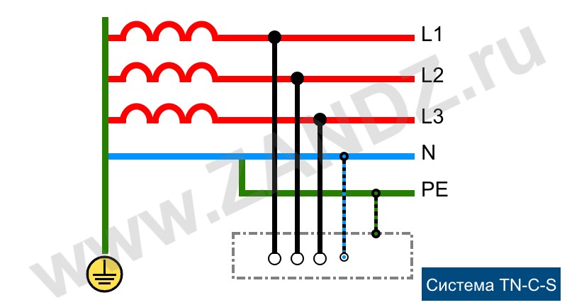
In a TN-C-S system (Figure 3), the neutral and protective functions must be integrated into a single conductor (PEN) from the solidly earthed source to the consumer’s intake. It is advisable to establish many connections to the ground along the PEN conductor.
在 TN-C-S 系统(图 3)中,从直接接地的电源侧到用户进线端,中性线与保护线功能需集成到一根 PEN 线中。建议沿 PEN 线设置多处接地连接。
In the consumer’s installation, the neutral and protective conductors must be maintained separately.
在用户设备内部,中性线与保护线必须保持分离。
The TN-C-S system is referred to as a “protective multiple earthed” (PME) system. The PEN conductor, known as a combined neutral and earth (CNE) conductor, is grounded at both the source and the terminals of the distribution mains, as well as at other intermediate places, thereby indicating multiple earthing.
TN-C-S 系统也被称为“保护多接地(PME,Protective Multiple Earthed)系统”。其中的 PEN 线又称为“中性接地组合线(CNE,Combined Neutral and Earth)”,需在电源侧、配电干线端子处以及其他中间位置进行接地,即实现“多接地”。
The multiple earthing of the CNE conductor guarantees that, in the event of an open circuit, exposed conductive parts remain grounded; consequently, the supply voltage between the installation line and neutral conductors is significantly diminished, leading to unacceptable voltage fluctuations for consumers.
CNE 线的多接地设计可确保:即便 CNE 线发生开路,外露导电部件仍能保持接地状态;但同时,设备相线与中性线之间的供电电压会大幅降低,进而导致用户侧出现不可接受的电压波动。
TT installation system
TT 设备接地系统
Lastly there is the TT system which uses mother earth as part of the earth return.
最后介绍 TT 系统,该系统将大地(mother earth)作为接地回流路径的一部分。
The neutral and the earthed parts are only connected together via an electrode system back to the source earth (and neutral). To check that conventional systems are satisfactory, i.e. that the protection operates on the occurrence of an earth fault, it is necessary to calculate the earth fault loop impedance (ZsZ_sZs) and ensure that the fault current through it will cause the protection to operate.
中性线与接地部件仅通过接地极系统连接,并最终回到电源侧接地(及中性线)。为验证传统系统是否满足要求(即接地故障发生时保护装置能可靠动作),需计算接地故障回路阻抗(ZsZ_sZs),并确保通过该阻抗的故障电流足以使保护装置动作。
This is quite a tedious process, involving as it does the calculation of the impedances afforded not only by the earth return but also by:
该计算过程较为繁琐,需计算的阻抗不仅包括接地回流路径的阻抗,还包括以下各部分的阻抗:
- The phase conductor
相线阻抗; - Supply transformer
供电变压器阻抗; - Supply network
供电网络阻抗; - Any neutral impedance.
所有中性线阻抗。
This information must be requested early. The Electricity Distributor should be able to give the fault level or the equivalent impedance of the supply network and the manufacturer can provide the appropriate impedances for the transformer. However, time will be required to obtain the answers so enquiries should be made at the commencement of the project.
上述信息需提前获取:配电商(Electricity Distributor)应能提供供电网络的故障等级或等效阻抗,变压器制造商可提供变压器的相应阻抗参数。但获取这些信息需要时间,因此应在项目启动时就发起咨询。
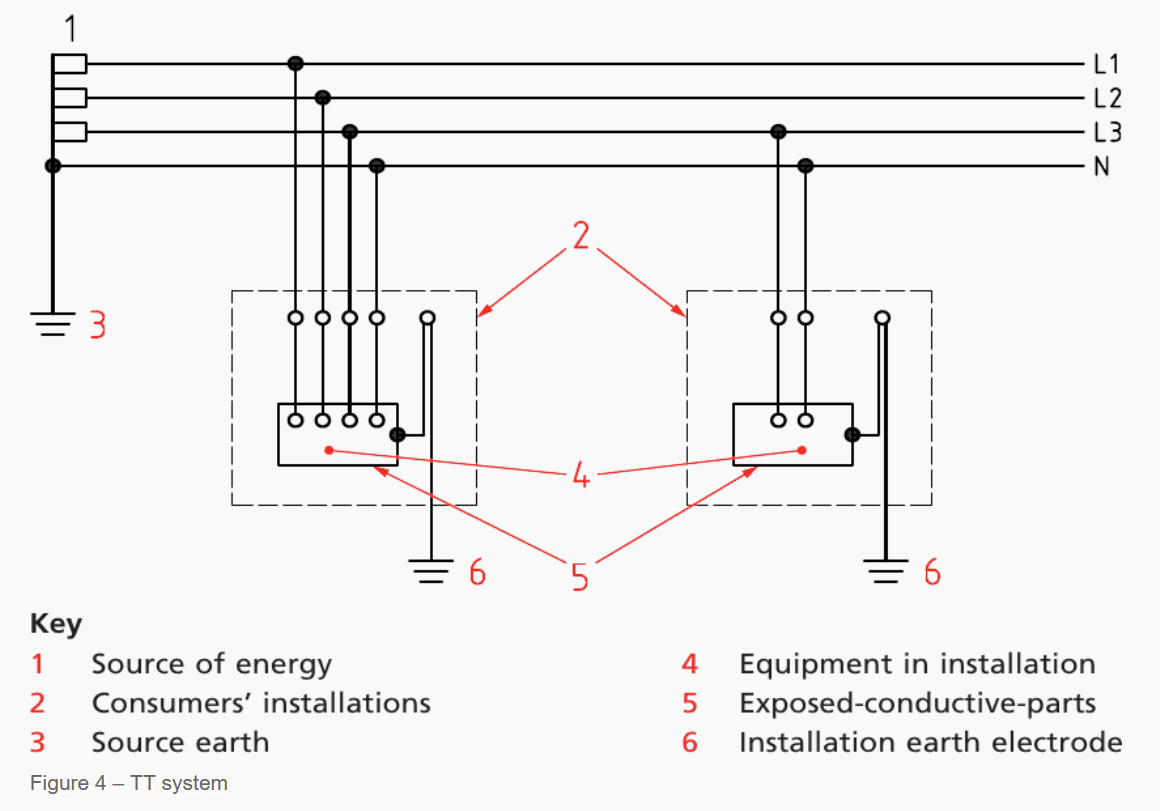
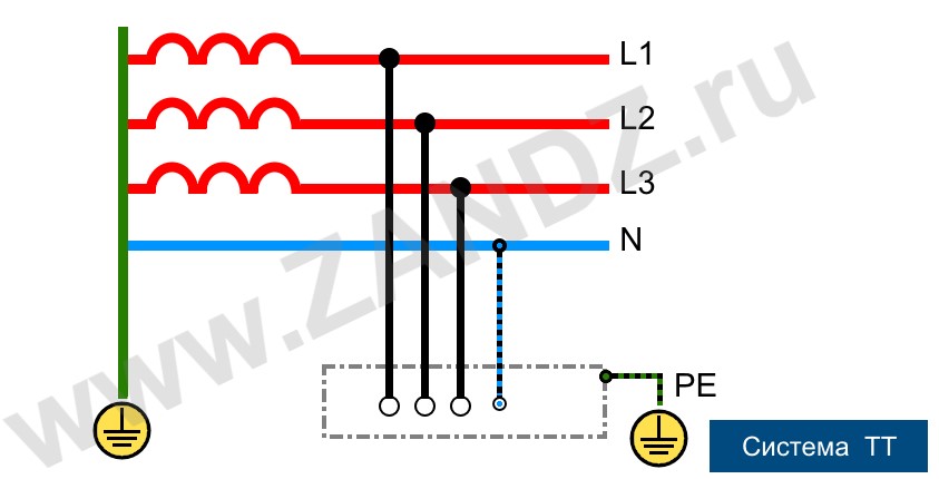
A TT system (Figure 4) features a solidly earthed source; the exposed conductive elements of the consumer’s installation are grounded via an installation earth electrode that is electrically independent of the source earth.
TT 系统(图 4)的特点是电源侧直接接地;用户设备的外露导电部件通过“设备接地极”接地,且该接地极与电源侧接地在电气上相互独立。
In the TT system, the earth fault loop impedance usually increases due to the presence of both the supply’s earth electrode resistance and the consumer’s installation’s earth electrode resistance in the fault path.
在 TT 系统中,由于故障路径中同时存在“供电侧接地极电阻”和“用户设备接地极电阻”,接地故障回路阻抗通常会增大。
Figure 4 – TT system
Earthing Study and Testing
接地研究与测试
The substation will house the circuit breakers of fuses for the main cable connections to the sub-distribution boards and motor control centres. These protective devices must discriminate with those further down the line nearer the ultimate loads. A system study must therefore establish the correct ratings of the substation equipment to discriminate with the distribution network.
变电站内设有断路器或熔断器,用于主电缆与分配电柜及电机控制中心的连接。这些保护装置必须与线路下游(靠近最终负载处)的保护装置实现“选择性配合(discriminate)”。因此,需通过系统研究确定变电站设备的正确额定值,以确保其与配电网络的保护装置实现选择性配合。
Earthing of equipment should be electrically complete and confirmed mechanically sound and tight.
设备接地应保证电气通路完整,并需确认接地连接在机械上牢固、紧密。
Figure 5 – Earthing bolt on the switchboard roof
图 5——配电盘顶部的接地螺栓
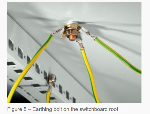
Earthing bolt on the switchboard roof
配电盘顶部的接地螺栓
Earthing conductors (previously termed earth leads) must be checked for compliance with the IEE Regulations, i.e. they must not be aluminium and they must be not less than 25mm225 \, \text{mm}^225mm2 for copper and 50mm250 \, \text{mm}^250mm2 for steel, unless they are protected against corrosion. These conductors are for connection to the earth electrodes.
接地导体(曾称为“接地线 earth leads”)必须符合 IEE 规程(IEE Regulations)要求:即接地导体不得采用铝材;若为铜材,截面积不得小于 25mm225 \, \text{mm}^225mm2;若为钢材,截面积不得小于 50mm250 \, \text{mm}^250mm2(防腐蚀处理的接地导体除外)。此类导体用于连接接地极。
The protective conductors previously known as earth continuity conductors must also comply with BS 7671 (the IEE Regulations) and in general for phase conductors of less than 16mm216 \, \text{mm}^216mm2; this means the protective conductors must be the same size as the phase conductors. When the phase conductor is above 16mm216 \, \text{mm}^216mm2 then the protective conductor remains at 16mm216 \, \text{mm}^216mm2 until the phase conductor is 35mm235 \, \text{mm}^235mm2, after which the protective conductor should be half the cross-sectional area of the phase conductor.
曾称为“接地连续导体(earth continuity conductors)”的保护导体,也必须符合 BS 7671 标准(即 IEE 规程):通常,若相线截面积小于 16mm216 \, \text{mm}^216mm2,保护导体截面积需与相线一致;若相线截面积超过 16mm216 \, \text{mm}^216mm2,则在相线截面积不超过 35mm235 \, \text{mm}^235mm2 时,保护导体截面积仍保持 16mm216 \, \text{mm}^216mm2;若相线截面积超过 35mm235 \, \text{mm}^235mm2,保护导体截面积应取相线截面积的一半。
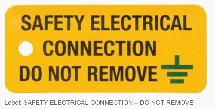
Another important point to bring out is that the earthing conductor to the earth electrode must be clearly and permanently labelled ‘SAFETY ELECTRICAL CONNECTION – DO NOT REMOVE’ and this should be placed at the connection of conductor to the electrode.
另一个重要注意事项:连接接地极的接地导体必须带有清晰且永久的标识,标识内容为“SAFETY ELECTRICAL CONNECTION – DO NOT REMOVE(安全电气连接——禁止拆除)”,且标识应贴在导体与接地极的连接部位。
Figure 6 – Label: SAFETY ELECTRICAL CONNECTION – DO NOT REMOVE
图 6——标识:安全电气连接——禁止拆除
Fuse ratings should also be checked in relation to other fuse ratings in the supply circuit or against the settings of protective relays to assure correct sequence of operation and discrimination. Circuit charts for distribution boards should be completed and designation labels fitted to ensure safe operation of switches and isolators.
还需核对熔断器的额定值:需结合供电回路中其他熔断器的额定值,或对照保护继电器的整定值进行核对,以确保保护装置动作顺序正确且具备选择性。分配电柜的电路图应绘制完整,并张贴标识标签,以确保开关和隔离开关的安全操作。
All tests should be carried out as required in BS 7671, Part 7, and an Electrical Installation Certificate given by the contractor to the person ordering the work.
所有测试均应按照 BS 7671 标准第 7 部分的要求执行,且承包商需向委托方提供《电气安装证书(Electrical Installation Certificate)》。
Many installations now incorporate rcds and fault current operated protective devices. These also must be tested using appropriate test equipment, full details of which can be found in BS 7671 or for more elaborate apparatus in BS 7430 and Guidance Notes which are published separately and amplify the requirements in the British Standard.
目前,许多设备中都集成了剩余电流装置(rcds,Residual Current Devices)和故障电流动作保护装置。此类装置也需使用适当的测试设备进行测试,详细测试要求可参考 BS 7671 标准;对于更复杂的设备,可参考 BS 7430 标准及单独出版的《指南注释(Guidance Notes)》,后者对英国标准(British Standard)的要求进行了补充说明。
The nominal voltages at present are:
当前的额定电压规定如下:
-
230V+10%230 \, \text{V} + 10\%230V+10% and −6%-6\%−6%
230V230 \, \text{V}230V(允许偏差:+10%、-6%); -
400V+10%400 \, \text{V} + 10\%400V+10% and −6%-6\%−6%
400V400 \, \text{V}400V(允许偏差:+10%、-6%)。
Protective equipotential bonding
保护等电位联结
The safety protocol of automated supply termination necessitates:
“电源自动切断”安全规程需满足以下要求:
-
Automated disconnection upon detection of an earth fault;
检测到接地故障时自动切断电源; -
Protective earthing (to enable this); and
保护接地(为实现电源自动切断提供条件); -
Implementation of protective equipotential bonding to mitigate contact voltages.
实施保护等电位联结,以降低接触电压。
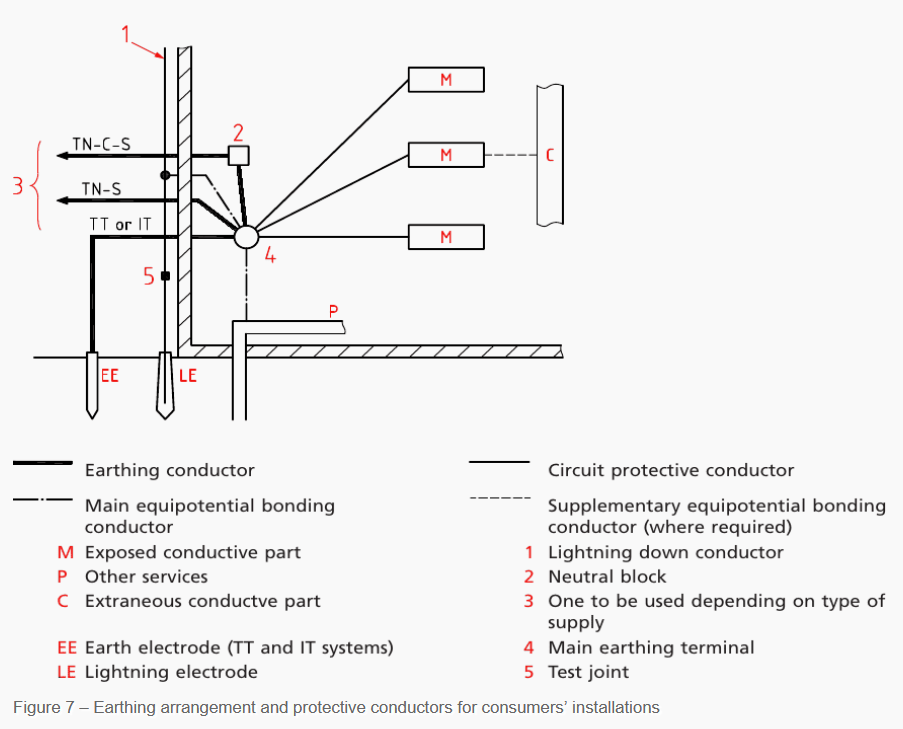
In instances when automated termination of power is implemented, protective equipotential bonding is advised, irrespective of the supply system type (see to Figure 7). It is advisable to bind extraneous conductive elements to the main earthing terminal of the installation using primary equipotential bonding conductors.
在采用“电源自动切断”的场景中,无论供电系统类型如何,均建议实施保护等电位联结(参见图 7)。建议通过“主等电位联结导体”将“外来导电部件(extraneous conductive elements)”与设备的总接地端子连接。
These extraneous conductive parts comprise:
上述外来导电部件包括:
- Plumbing pipes for water installation;
给水系统水管; - Gas installation piping;
燃气系统管道; - Additional installation piping and ductwork;
其他设备的管道及风管; - Central heating and air conditioning systems;
集中供暖与空调系统; - Exposed metallic components of the building framework; and
建筑结构的外露金属部件; - Additional metallic components including cable trays and cable ladder racks.
其他金属部件(如电缆托盘、电缆梯架)。
The connection of a lightning protection system to the protective equipotential bonding must comply with BS EN 62305-4. NOTE 2 BS EN 62305-4 mandates the establishment of a bond between the lightning protection system and the installation’s equipotential bonding system. The obligation to define and implement this bond lies with the entity accountable for the lightning protection system.
防雷系统与保护等电位联结的连接必须符合 BS EN 62305-4 标准。注 2:BS EN 62305-4 标准强制要求“防雷系统”与“设备等电位联结系统”之间建立联结,且该联结的设计与实施责任由防雷系统的负责单位承担。
When both primary gas and water pipes approach a site, a common bonding conductor may be utilized; however, this conductor must be continuous or permanently joined (by soldering or crimping) to maintain continuity. A bonding conductor may also be utilized in conjunction with other external conducting components.
若主燃气管与主给水管同时进入场地,可采用“共用联结导体”;但该导体必须保持连续,或通过焊接(soldering)、压接(crimping)等方式实现永久连接,以确保电气连续性。联结导体也可用于连接其他外部导电部件。
The primary equipotential bonding connections to the water and gas pipelines should be established as close as feasible to their entrance points into the premises. If an insulating section or insert is present, the bonding connection must be established to the metallic pipes on the consumer’s side of the section or insert, prior to the branch pipework.
与水管、燃气管连接的主等电位联结,应在管道进入建筑物的入口处附近尽可能靠近入口的位置进行。若管道中存在绝缘段或绝缘插件,则联结必须在“绝缘段/插件的用户侧”进行,且需在管道分支前完成。
The connection should be established, if feasible, within 600mm600 \, \text{mm}600mm of the meter outlet union or at any access point to the building if the meter is located externally (see to BS 7671:2008+A1, Regulation 544.1.2).
若条件允许,联结应在“仪表出口接头”的 600mm600 \, \text{mm}600mm 范围内进行;若仪表安装在室外,则联结可在建筑物的任意入口处进行(参见 BS 7671:2008+A1 标准第 544.1.2 条规定)。
Figure 7 – Earthing arrangement and protective conductors for consumers’ installations
图 7——用户设备的接地装置与保护导体
Earthing arrangement and protective conductors for consumers’ installations
用户设备的接地装置与保护导体
Figure 7 – Earthing arrangement and protective conductors for consumers’ installations
图 7——用户设备的接地装置与保护导体
Reference:
- Handbook of electrical installation practice fourth edition – Eur Ing GEOFFREY STOKES
《电气安装实务手册(第四版)》——欧洲工程师杰弗里·斯托克斯(Eur Ing GEOFFREY STOKES)著
TN-S, TN-C, TNC-S, TT, IT grounding systems
TN-S、TN-C、TNC-S、TT、IT 接地系统
When designing, erecting and operating electrical installations, industrial and domestic electrical equipment, as well as electric lighting systems, one of the fundamental factors in ensuring their functionality and electrical safety is precisely designed and properly carried out grounding. Basic requirements for grounding systems are contained in para. 1.7 of the Electrical Installations Code (PUE). Depending on how the respective wires, device housings, equipment or certain points of the network are connected and with what grounding structures, devices or objects they are connected, the grounding systems are divided into natural and artificial grounding.
在设计、安装和运行电气装置、工业及民用电气设备以及电气照明系统时,确保其功能性和电气安全性的关键因素之一,是设计精准且施工规范的接地装置。接地系统的基本要求包含在《电气装置规范》(PUE)第 1.7 节中。根据相关导线、设备外壳、电气设备或电网特定节点的连接方式,以及它们所连接的接地结构、装置或物体的不同,接地系统可分为自然接地和人工接地两类。
Natural grounding is any metal objects residing in the soil, i.e. piles, pipes, fittings, and other conductive products. However, due to the fact that the electrical resistance to the spread of electric current in the soil and electric charges of these objects are difficult to control and predict, the use of natural ground during the operation of electrical equipment is prohibited. Regulatory documents allow only the use of artificial grounding, where all connections are made to specially created grounding devices.
自然接地指的是埋于土壤中的各类金属物体,例如桩体、管道、管件及其他导电构件。然而,由于这些物体在土壤中的电流扩散电阻和电荷难以控制与预测,电气设备运行期间禁止使用自然接地。规范性文件仅允许使用人工接地,即所有连接均接入专门设置的接地装置。
The main standardized parameter that shows how well grounding is carried out is its resistance. The resistance to current spreading entering the soil through the ground electrode system is controlled here. The value of grounding resistance depends on the type and condition of the soil, as well as design features and the materials used to build the grounding device. The determining factor that affects the value of the ground electrode system resistance is the area of direct contact of its plates, rods, tubes and other electrodes with the soil.
衡量接地效果的核心标准化参数是接地电阻,此处需控制的是电流通过接地极系统流入土壤时的扩散电阻。接地电阻值取决于土壤类型与状态、接地装置的设计特性及所用材料。影响接地极系统电阻值的决定性因素,是其极板、接地棒、接地管及其他电极与土壤的直接接触面积。
Types of artificial grounding systems
人工接地系统的类型
The main document regulating the use of different earthing systems in Russia is PUE (paragraph 1.7) developed in accordance with the principles, classification and methods of grounding systems design approved by a special protocol of the International Electrotechnical Commission (IEC). Abbreviations of grounding systems are usually denoted by a combination of the first letters of the French words: «Terre» - gound, «Neuter» - neutral, «Isole» - to isolate, as well as the English words: «combined» and «separated».
俄罗斯规范各类接地系统使用的核心文件是《电气装置规范》(PUE 第 1.7 节),该规范依据国际电工委员会(IEC)专项协议批准的接地系统设计原则、分类及方法制定。接地系统的缩写通常由法语单词首字母(“Terre”表示接地、“Neuter”表示中性线、“Isole”表示隔离)及英语单词首字母(“combined”表示组合、“separated”表示分开)组合构成。
T - Grounding.
T - 接地(法语“Terre”缩写)
N - Connection to neutral.
N - 接中性线(法语“Neuter”缩写)
I - Isolation.
I - 隔离(法语“Isole”缩写)
C - combined functions: combining the functional and protective neutral wires.
C - 功能组合:即功能中性线与保护中性线合一
S - The separate use of functional and protective neutral wires throughout the entire grid.
S - 全电网内功能中性线与保护中性线分开使用
In the following names of artificial grounding systems, you can define the way the electrical power source (generator or transformer) is grounded by the first letter and the consumer - by the second letter. TN, TT and IT system are distinguished. The first of which, in turn, is used in three different versions: TN-C, TN-S, TN-CS. To understand the differences and the structure of the systems let’s consider each of them in more detail.
在以下人工接地系统的名称中,第一个字母代表电源(发电机或变压器)的接地方式,第二个字母代表用电设备的接地方式,据此可区分出 TN、TT 和 IT 三种系统。其中,TN 系统又分为 TN-C、TN-S、TN-C-S 三种不同形式。为明确各系统的差异与结构,下文将对每种系统进行详细说明。
1. Dead-grounded neutral systems (TN grounding systems)
直接接地中性线系统(TN 接地系统)
This is the designation for systems in which a common dead-grounded neutral of a generator or step-down transformer is used to connect functional and protective conductors. Thus, all conductive housing parts and screens of consumers should be connected to a common neutral wire connected to this neutral. In accordance with GOST R50571.2-94, zero protective conductors of various types are also marked with the following Latin letters:
该类系统以发电机或降压变压器的公共直接接地中性线作为功能导体与保护导体的连接点,因此用电设备的所有导电外壳部件及屏蔽层均需连接至与该中性线相连的公共中性线。依据 GOST R50571.2 - 94 标准,各类保护零线还需用以下拉丁字母标识:
-
N - Functional neutral;
N - 功能中性线; -
PE - Protective neutral;
PE - 保护中性线; -
PEN - Combination of functional and protective zero conductors.
PEN - 功能零线与保护零线的组合导体。
TN system built using a dead-grounded neutral is characterized by a connection of functional neutral - conductor N (neutral) - to the ground loop installed near the transformer substation. Obviously, in this system, the neutral grounding by a special compensatory device, arc suppression coil, is not used. In practice, three sub-types of the TN system are used: TN-C, TN-S and TN-CS, which differ by various ways of connecting to N and PE ground conductors.
采用直接接地中性线的 TN 系统,其特点是功能中性线(导体 N,即中性线)与变电站附近设置的接地网相连。显然,该系统不采用消弧线圈这类特殊补偿装置进行中性线接地。实际应用中,TN 系统分为 TN-C、TN-S 和 TN-C-S 三种亚型,它们的区别在于与 N 线和 PE 接地线的连接方式不同。
TN-C grounding system
TN-C 接地系统
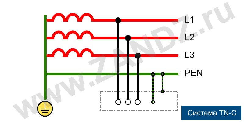
As the letter designation suggests, TN-C system is characterized by the combination of functional and protective neutral conductors. A classical TN-C system is a traditional four-wire power supply circuit with three phases and one neutral wire. In this case, the main grounding bus is a dead-grounded neutral. All the open parts, housings and metal parts of devices that can conduct electric current should be connected to the bus using additional neutral wires.
从字母标识可看出,TN-C 系统的特点是功能中性线与保护中性线合一。典型的 TN-C 系统是传统的三相四线制供电回路,包含三根相线和一根中性线。在此系统中,主接地母线为直接接地的中性线,设备所有暴露的导电部件、外壳及金属构件均需通过额外的中性线连接至该母线。
This system has several significant drawbacks, and the most serious among them is the loss of safety functions in case of breakage or burn-off of the neutral wire. In such cases, dangerous voltages occur on the bare surfaces of instrument and equipment housings. As a separate PE protective ground conductor is not used in this system, all the connected sockets have no ground. Therefore, all the electrical equipment should be connected to neutral, i.e. the housing parts should be connected to a neutral wire.
该系统存在若干明显缺陷,其中最严重的是:当中性线断裂或烧断时,系统将丧失安全保护功能,此时仪器和设备外壳的裸露表面会出现危险电压。由于系统未设置独立的 PE 保护接地线,所有连接的插座均无接地端,因此所有电气设备都需接中性线,即设备外壳部件需连接至中性线。
Such type of connection provides that if a phase conductor touches the housing, a short-circuit triggers a circuit breaker. Thus, the danger of electric shock to people or fire of sparking equipment will be eliminated by the emergency power cutoff. An important limitation related to a forced neutral connection of domestic appliances powered by the TN-C system is that the use of additional potential equalization circuits in the bathrooms is prohibited, and all residents should know this.
这种连接方式的作用是:当相线接触设备外壳时,短路电流会触发断路器动作,通过紧急切断电源消除人员触电或设备放电起火的危险。对于采用 TN-C 系统供电、且外壳强制接中性线的家用电器,有一项重要限制:卫生间内禁止使用额外的电位均衡电路,所有住户均需知晓这一规定。
Currently, such grounding systems can be found in houses belonging to the old housing stock. But they are also used in the street lighting networks, where the risk is minimal.
目前,此类接地系统多见于老旧住宅建筑,同时也用于风险极低的道路照明网络中。
TN-S system
TN-S 系统
A more progressive and safe compared to the TN-C system, TN-S system with separate neutral and protective conductors was developed and introduced in the 1930s. This solution ensures a high level of electrical safety of people and equipment. It has one, although a very significant drawback - the high cost. Since functional (N) and protective (PE) neutrals are separated at a substation itself, the three-phase voltage supply is performed via five wires; and single-phase voltage is supplied via three wires. To connect both neutral conductors at the source side, the generator’s or transformer’s dead-grounded neutral is used.
TN-S 系统于 20 世纪 30 年代研发并投入使用,其采用中性线与保护线分离的设计,相比 TN-C 系统更先进、更安全,能为人员和设备提供高水平的电气安全保障。但该系统存在一个显著缺陷——成本较高:由于功能中性线(N 线)与保护中性线(PE 线)在变电站内就已分开,三相供电需通过五根导线实现,单相供电则需通过三根导线实现;电源侧的两根中性线(N 线和 PE 线)均连接至发电机或变压器的直接接地中性线。
GOST R50571 and an updated edition of PUE provides that all critical sites, as well as energy supply buildings under construction or renovation, shall have TN-S system installed, as it provides a high level of electrical safety. Unfortunately, the wide use and implementation of the TN-S system is hindered by a high level of costs and the orientation of the Russian energy sector on the three-phase four-wire power supply.
GOST R50571 标准及《电气装置规范》(PUE)修订版规定,所有关键场所及新建或翻新的供能建筑均需安装 TN-S 系统,因其能提供高水平的电气安全保障。遗憾的是,高昂的成本以及俄罗斯能源行业对三相四线制供电的依赖,阻碍了 TN-S 系统的广泛推广与应用。
TN-C-S system
TN-C-S 系统
In order to decrease the cost of secure but capital-intensive TN-S system with separate N and PE neutral conductors, a solution was developed that allows using its advantages with a smaller budget, slightly higher than that of the TN-C system. The principle of this connection method is that the substation supplies power using a combined PEN neutral connected to the dead-grounded neutral. At the input to the building this neutral splits into a PE protective neutral, and another conductor that works as functional N neutral on the side of the consumer.
TN-S 系统虽安全但成本高昂(因 N 线与 PE 线分离),为降低其成本,业界研发出 TN-C-S 系统——该系统能以略高于 TN-C 系统的预算,发挥 TN-S 系统的优势。其连接原理为:变电站通过与直接接地中性线相连的 PEN 组合中性线供电;在建筑进线处,该 PEN 线分为两根导线,一根作为 PE 保护中性线,另一根作为用电侧的功能中性线(N 线)。
This system has a significant drawback: in the event of breakage or burn-off of the PEN conductor in the “substation - building” section, dangerous voltages occur on the PE conductor, and, consequently, on all housing parts of electric appliances. Therefore, when a TN-C-S is used, which is quite common, regulations require the implementation of special measures to protect the PEN conductor from damage.
该系统存在一个显著缺陷:若“变电站 - 建筑”段的 PEN 导体发生断裂或烧断,PE 导体上会出现危险电压,进而导致所有电气设备的外壳部件带电。因此,尽管 TN-C-S 系统应用广泛,但规范要求使用该系统时,必须采取特殊措施保护 PEN 导体免受损坏。
TT grounding system
TT 接地系统
When the power is supplied via overhead lines widespread in rural areas, then if the unsafe TN-C-S system is used, it is difficult to ensure the adequate protection of the PEN combined neutral conductor. TT systems are more and more used in such areas. They require the dead-grounding of the source neutral and the transfer of three-phase voltage over four wires. The fourth wire is a functional N neutral. A local, usually module-rode ground electrode system is installed on the side of the consumer, and all the protective neutral PE wires linked to the housing parts are connected to it.
在农村地区广泛使用架空线路供电的场景中,若采用安全性不足的 TN-C-S 系统,难以对 PEN 组合中性线提供充分保护,因此 TT 系统在这类地区的应用日益广泛。TT 系统要求电源中性线直接接地,三相电压通过四根导线传输(第四根导线为功能中性线 N 线);用电侧需设置本地接地极系统(通常为模块式接地棒),所有连接设备外壳的保护中性线(PE 线)均需接入该接地极系统。
Recently approved for the use in the Russian Federation, this system is rapidly spreading in the Russian provinces and is often used to power private households. In urban areas, TT is often used to power the points of street trade. With this method of grounding, circuit breakers and lightning protection are mandatory.
TT 系统近期已获准在俄罗斯联邦境内使用,目前正在俄罗斯各地区快速推广,常用于为私人住宅供电;在城市地区,TT 系统常为街头商业网点供电。采用该接地方式时,断路器和防雷保护装置为强制配置。
2. Isolated neutral system
中性点不接地系统
In all systems described above, the neutral is connected to the ground, which makes them rather robust. Still they all have a number of significant drawbacks. Much more advanced and safe are systems that use an isolated neutral either absolutely not connected with the ground or grounded with the help of special equipment and devices with high resistance. For example, as in IT system. These connection methods are often used in medical facilities to power life-support equipment, in oil refineries and power plants, research laboratories with very sensitive instruments, and in other mission-critical facilities.
上述所有系统的中性线均接地,虽具备一定稳定性,但仍存在诸多显著缺陷。而采用中性点不接地(或通过高电阻特殊设备接地)的系统更为先进、安全,IT 系统便是典型代表。这类接地方式常用于为医疗场所的生命支持设备供电,也应用于炼油厂、发电厂、配备高灵敏度仪器的研究实验室及其他关键设施。
IT system
IT 系统
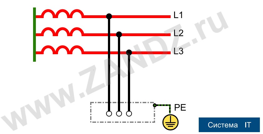
This is a classical system, the main feature of which is an isolated neutral of the source - I, as well as a protective ground loop T on the side of the consumer. The voltage from the source to the consumer is transmitted over the lowest possible number of wires, and all conductive parts of the consumer equipment housings must be securely connected to the ground electrode system. There is no functional neutral conductor N on the “source - consumer” section in the IT system architecture
IT 系统是典型的中性点不接地系统,其核心特点为:电源中性点隔离(标识“I”),且用电侧设置保护接地回路(标识“T”)。电源至用电设备的电压传输采用最少数量的导线,用电设备外壳的所有导电部件均需可靠连接至接地极系统。在 IT 系统的架构中,“电源 - 用电设备”段不存在功能中性线(N 线)。
Reliable grounding is guaranteed security
可靠接地是安全的保障
All existing types of grounding systems are designed to ensure the reliable and safe operation of electrical appliances and equipment connected on the side of the consumer, as well as the protection people that use this equipment against electric shock. When designing and installing power supply systems with both functional and protective grounding as their integral components, the possibility of occurrence of dangerous voltages on conductive housings of devices and industrial equipment should be reduced to a minimum.
现有所有类型的接地系统,其设计目的均为保障用电侧电气设备的可靠安全运行,并保护设备使用者免受触电伤害。在设计和安装包含功能接地与保护接地(二者均为系统必要组成部分)的供电系统时,需将设备及工业装置导电外壳出现危险电压的可能性降至最低。
The grounding system must either remove the dangerous potential from a surface of an object or ensure the smooth operation of protective devices with a minimum of delay. In each case, technical perfection, or vice versa, the lack of perfection of a grounding system, may cost human life.
接地系统需具备两种功能之一:要么消除物体表面的危险电位,要么确保保护装置无延迟顺畅动作。无论何种情况,接地系统的技术完善与否,都可能关系到人的生命安全。
TT、IT、TN-C、TN-S、TN-C-S 低压接地系统全面解析
电气设计狄老师
低压配电接地系统的选择应根据具体的供电系统进行准确判断,同时对电线、电缆的选择也有严格要求。若不符合要求,可能会造成严重后果。因此,各单位在进行电气工程安装时,必须高度重视低压配电中的接地系统工作。
一、低压供电系统接地方式及其特点
低压配电系统的接地形式分为三种:TN 系统、TT 系统和 IT 系统。字母表示的含义是:第一个字母表示电源对地的关系,第二个字母表示电气设施的外露可导电部分对地的关系,第三、四两个字母表示中性线和保护线的组合情况。
TT 系统是将电气设备的金属外壳作接地保护的系统;TN 系统是将电气设备的金属外壳作接零保护的系统。
(1)TT 方式供电系统
TT 方式供电系统是指将电气设备的金属外壳直接接地的保护系统,称为保护接地系统,也称 TT 系统。
第一个符号 T 表示电力系统中性点直接接地;第二个符号 T 表示负载设备外露不与带电体相接的金属导电部分与大地直接联接,而与系统如何接地无关。
TT 系统是电源中性点直接接地,用电设备外露可导电部分也直接接地的系统。通常将电源中性点的接地称为工作接地,而设备外露可导电部分的接地称为保护接地。
TT 系统中,这两个接地必须是相互独立的。设备接地可以是每一设备都有各自独立的接地装置,也可以是若干设备共用一个接地装置。
(2)TN 方式供电系统
TN 方式供电系统是将电气设备的金属外壳与工作零线相接的保护系统,称作接零保护系统,用 TN 表示。其特点如下:
一旦设备出现外壳带电,接零保护系统能将漏电电流上升为短路电流,这个电流很大,是 TT 系统的 5.3 倍,实际上就是单相对地短路故障,熔断器的熔丝会熔断,低压断路器的脱扣器会立即动作而跳闸,使故障设备断电,比较安全。
TN 系统节省材料、工时,在我国和其他许多国家广泛得到应用,可见比 TT 系统优点多。TN 方式供电系统中,根据其保护零线是否与工作零线分开而划分为 TN-C 和 TN-S 等两种。
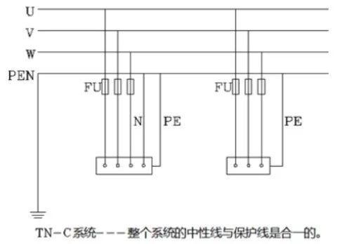
a. TN-C 方式供电系统
TN-C 系统是保护接零系统,其中的零线为 PEN 线,即当工作零线又当保护零线,既与电源开关接又与电气设备金属外壳相连。当总零线断掉,那单相负载无法构成回路,零线电压增高,与此相连的金属外壳设备也带电,很危险。所以必须让零线重复接地,零线断了后,TN-C 变成 TT 保护方式,单相供电变成一火一地,减轻了危险。
TN-C 供电系统的特点如下:
- 由于三相负载不平衡,中性线上有不平衡电流,对地有电压,所以与保护线所连接的电气设备金属外壳有一定的电压。
- 如果中性线断线,则保护接零的剩余电流设备外壳带电。
- 如果电源的相线碰地,则设备的外壳电位升高,使中性线上的危险电位蔓延。
- TN-C 系统干线上使用剩余电流保护器时,中性线后面的所有重复接地必须拆除,否则剩余电流开关合不上;而且,中性线在任何情况下都不得断线。所以,实用中性线只能让剩余电流保护器的上侧有重复接地。
- TN-C 方式供电系统只适用于三相负载基本平衡情况。
b. TN-S 方式供电系统
在 TN-S 制式的供电系统中,B 级(基本保护)的防雷器我们选用 3 + 1 电路结构的防雷器。
在 3 + 1 电路里,3 根相线通过防雷器连接到中线,中线通过一个火花间隙连接到保护地(PE)线。
这种电路结构可预防由于绝缘问题而使接电线带电从而引起防雷器产生漏电电流的问题。
如果需要多级浪涌保护,那么必须在分配电箱里安装 C 级防雷器,即中等保护的防雷器。
对于间隙型防雷器,仅当前级断路器的容量大于防雷器要求的数值时,需要在防雷器前串接适当的断路器。
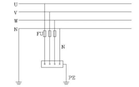
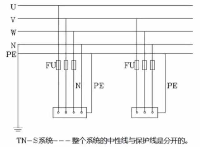
TN-S 方式供电系统是把工作零线 N 和专用保护线 PE 严格分开的供电系统,称作 TN-S 供电系统,TN-S 供电系统的特点如下:
- 系统正常运行时,专用保护线上没有电流,只是工作零线上有不平衡电流。PE 线对地没有电压,所以电气设备金属外壳接零保护是接在专用的保护线 PE 上,安全可靠。
- 工作零线只用作单相照明负载回路。
- 专用保护线 PE 不许断线,也不许进入漏电开关。
TN-S 系统即三相五线供电系统,除三相线(U、V、W)和中性线(N)外,还有一条保护接地(PE)线。
-
谐波电流
当今社会的各类建筑物中的供电系统通常采用直流电子设备以及大量的荧光灯。运行过程会产生高次谐波,其不仅对电源具有严重的污染作用,而且还会给 N 线带来谐波电流,特别是 3 次谐波电流。
根据相关理论的分析,出现在三相中的 3 次谐波电流会在 N 线上叠加,而叠加后的电流值相当可观。为了防止 N 线上出现叠加的谐波电流超过相线电流而出现的短路,供电过程中在三相四线回路中采用 4 根截面相等的电线或电缆。
-
单相工作电流
N 线上电流的大小与相线上的电流一致,单相工作电流会随着照度标准的变化而发生变化,如果电流越来越大,则很可能会产生严重的后果,所以不容小觑。
-
三相不平衡电流
三相不平衡电流是单相负荷的供电系统中必然会出现的情况。而且随着时间的推移,不平衡的现象会随之发展而变得愈加复杂。TN-S 系统供电的制定是特别针对三相不平衡用电负荷,从而防止因用电而出现的意外事故。
c. TN-C-S 方式供电系统
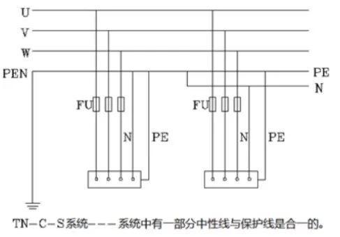
TN-C-S 方式供电系统在建筑施工临时供电中,如果前部分是 TN-C 方式供电,而施工规范规定施工现场必须采用 TN-S 方式供电系统,则可以在系统后部分现场总配电箱分出 PE 线。
TN-C-S 系统的特点如下:
-
工作零线 N 与专用保护线 PE 相联通,如图 1-5ND 这段线路不平衡电流比较大时,电气设备的接零保护受到零线电位的影响。
D 点至后面 PE 线上没有电流,即该段导线上没有电压降,因此,TN-C-S 系统可以降低电动机外壳对地的电压,然而又不能完全消除这个电压,这个电压的大小取决于 ND 线的负载不平衡的情况及 ND 这段线路的长度。负载越不平衡,ND 线又很长时,设备外壳对地电压偏移就越大。所以要求负载不平衡电流不能太大,而且在 PE 线上应作重复接地。
-
PE 线在任何情况下都不能进入漏电保护器,因为线路末端的漏电保护器动作会使前级漏电保护器跳闸造成大范围停电。
-
对 PE 线除了在总箱处必须和 N 线相接以外,其他各分箱处均不得把 N 线和 PE 线相联,PE 线上不许安装开关和熔断器,也不得用大地兼作 PE 线。
通过上述分析,TN-C-S 供电系统是在 TN-C 系统上临时变通的做法。当三相电力变压器工作接地情况良好、三相负载比较平衡时,TN-C-S 系统在施工用电实践中效果还是可行的。
但是,在三相负载不平衡、建筑施工工地有专用的电力变压器时,必须采用 TN-S 方式供电系统。
d. PE 线的作用及约束条件
常见的低压配电系统主要通过三种方式实现接地。在电气设备与供电系统相连的情况下,低压配电系统设计中把可触及到金属物体的所有电气设备均与保护 PE 线连接,可以对电气设备与操作人员形成保护。所以,在低压配电系统保护中,PE 线的设置非常重要,通过技术措施实现安全保护。
而 PE 线的设置要求具体包含以下几个方面:
- 载流能力能够达到保护装置灵敏度的要求。
- 载流时的线载温度以及电磁感应强度都应控制在合理范围内,不能存在对建筑物或其内部隐藏的危险,例如火灾或爆炸。
- 由于接地故障电流较小,TT 系统接地故障保护的约束条件为 ( R_A I_A \leq 50 \text{V} ),条件中的 ( R_A ) 指的是可导电部分的接地极电阻,( I_A ) 指的是保证保护电器在规定时间内切断故障线的动作电流。
(3)IT 方式供电系统
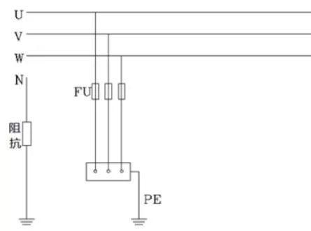
IT 系统是指在电源中性点不接地系统中,将所有设备的外露可导电部分均经各自的保护线 PE 分别直接接地,称之为 IT 供电系统。IT 系统一般为三相三线制。也就是说电源的中性点是对地绝缘的或者通过高阻抗接地。
IT 方式供电系统 I 表示电源侧没有工作接地。第二个字母 T 表示负载侧电气设备进行接地保护。
IT 方式供电系统在供电距离不是很长时,供电的可靠性高、安全性好。一般用于不允许停电的场所,或者是要求严格地连续供电的地方,例如电炉炼钢、大医院的手术室、地下矿井等处。
IT 系统发生接地故障时,接地故障电压不会超过 50V,不会引起相间电击的危险。
二、TT、TN 系统在应用中需要注意的事项
(一)TT 系统中性线不应重复接地
在一些供配电工程中,承建部门要求将 TT 系统中性线做重复接地,其目的是防止中性线断线后中性点漂移带来的三相电压不平衡。实际上,该做法效果有限。
(二)农村低压电网不应采用 TN-C 系统
- TN-C 系统的单相回路内,如果 NPE 线中断,电气设备外壳可带高达 220V 的对地电压,威胁人身安全。
- TN-C 系统的三相回路内,如果 NPE 线中断,不仅使设备失去等电压联结和接地,在三相不平衡时还因“断零”而引起烧坏单相设备事故。
- TN-C 系统 NPE 线不平衡电流产生的电压,将在电气装置内产生电位差和杂散电流,容易打火和干扰电子设备。
发布于 2019-10-08 12:29
低压配电系统接地方式详解
1. 引言
1.1 接地系统的重要性
在低压配电系统中,接地是保障人身安全、设备正常运行及电力系统稳定性的关键措施。合理的接地方式能够有效防止人身伤害、设备和线路损坏和保障电力系统正常运行。常见的接地系统包括 TN、TT 和 IT,每种系统具有独特的结构特点和适用场景。
1.2 文章结构概述
本文将深入解析 TN、TT、IT 三种接地系统的原理、背景及实际应用,通过对比表格帮助读者快速掌握其核心差异。
2. TN 接地系统
2.1 定义与分类
TN 系统(Terre-Neutre)是指电源中性点直接接地,设备外露导电部分通过保护线(PE)与中性线(N)连接的系统。根据 PE 与 N 的组合方式,TN 系统分为以下三类:
2.1.1 TN-C 结构
- TN-C:PE 与 N 合并为 PEN 线,三相四线制。
2.1.2 TN-S 结构
- TN-S:PE 与 N 完全独立,三相五线制。
2.1.3 TN-C-S 结构
- TN-C-S:前段为 TN-C,后段为 TN-S,结合两者的特点。
2.2 工作原理
2.2.1 TN-C 原理
- 经济性:TN-C 系统中的 N 线和 PE 线合并为 PEN 线,这使得系统结构更简洁。由于减少了导线数量,TN-C 系统在经济性上具有一定的优势。
- 安全性:由于 PEN 线在漏电保护器中漏电流相互抵消,导致漏电保护器不能发挥保护作用。此外,PEN 线接到设备金属外壳上可能导致设备外壳带电,存在安全隐患。
2.2.2 TN-S 原理
- 经济性:TN-S 系统中有专用的 N 线和 PE 线。由于导线数量变为 5 根,TN-S 系统在经济性上不具有优势。
- 安全性:系统正常运行时,专用保护线上没有电流,只是工作零线上有不平衡电流。电气设备金属外壳接零保护是接在专用的保护线 PE 上,安全可靠。
2.2.3 TN-C-S 原理
- 工作中性线 N 与专用保护线 PE 连接。当线路不平衡电流较大时,电气设备的零保护受中性线电位的影响。TN-C-S 系统可以将电机外壳的电压降低到对地电压,但不能完全消除这个电压。该电压的大小取决于布线的负载不平衡和这条线路的长度。负载不平衡性越强,接线越长,设备外壳对地的电压偏移就越大。因此,要求负载不平衡电流不宜过大,并且 PE 线应反复接地。
- PE 线在任何情况下都不能进入漏电保护器,因为线路末端的漏电保护器会导致前部漏电保护器跳闸,造成大面积停电。
- 除一般箱内的 PE 线必须接 N 线外,N 线和 PE 线不得在其他隔间内接。PE 线路上不得安装开关和熔断器,不得将 PE 用作接地。
2.3 优缺点分析
| 类型 | 优点 | 缺点 |
|---|---|---|
| TN-C | 节省材料成本,结构简单;无需单独敷设 PE 线 | PEN 线断线可能导致设备外壳带电,安全性低 |
| TN-S | 安全性高,电磁干扰小 | 需单独敷设 PE 线,成本较高 |
| TN-C-S | 兼顾成本与安全,灵活性高 | 需确保 TN-C 与 TN-S 分段处的可靠连接 |
3. TT 接地系统
3.1 定义与结构
TT 系统(Terre-Terre)中,电源中性点直接接地,设备外露导电部分通过独立的接地装置接地,PE 线与电源中性点无直接连接。
第一个符号 T:电源系统的中性点直接接地;
第二个符号 T:负载设备外露不与带电体相接的导电部分与大地直接联接,与系统如何接地无关。
3.2 工作原理
- 安全性:当电气设备的金属外壳带电时(相线接触外壳或设备绝缘损坏漏电),接地保护可以大大降低触电的风险。
- 经济性:TT 系统的接地装置消耗大量钢材,难以回收。
3.3 优缺点分析
| 优点 | 缺点 |
|---|---|
| 独立接地,不受电网 PE 线影响;适合分散供电场景 | 需额外安装 RCD,成本较高;接地电阻要求严格,施工复杂 |
4. IT 接地系统
4.1 定义与结构
IT 系统(Isolé-Terre)中,电源中性点不接地或通过高阻抗接地,设备外露导电部分独立接地。
I:电源侧没有工作接地,或高阻抗接地。
T:负载侧电气设备已接地。
4.2 工作原理
IT 模式供电系统在供电距离不长时可靠性高,安全性好。它比电源的中性接地系统更安全。
但是,如果电源长时间使用,则不能忽视电源线对地的分布式电容。当短路故障或负载漏电导致器件外壳带电时,漏电流会形成一条通地路径,保护装置不一定动作。
4.3 优缺点分析
| 优点 | 缺点 |
|---|---|
| 供电连续性高,首次接地不跳闸;安全性高,触电风险低;适合易燃易爆环境 | 需配备绝缘监测系统,成本高昂;系统复杂度高,维护难度大 |
5. 接地系统对比表
| 系统类型 | 安全性 | 优点 | 缺点 | 经济性 | 典型应用场景 |
|---|---|---|---|---|---|
| TN-C | 较低(PEN 线断线时设备外壳带电风险高) | 1. 结构简单,节省材料成本 2. 无需单独敷设 PE 线 | 1. PEN 线故障可能导致触电 2. 电磁干扰较大 | 低(初期成本最低) | 老旧工业厂房、逐步淘汰的改造项目 |
| TN-S | 高(PE 与 N 独立,漏电时快速切断电源) | 1. 安全性高,触电风险低 2. 电磁兼容性好 | 1. 需独立敷设 PE 线,成本较高 2. 施工复杂 | 高(初期与维护成本高) | 商业建筑、数据中心、医院、高端制造业 |
| TN-C-S | 中高(前段 TN-C 节省成本,后段 TN-S 保障安全) | 1. 兼顾成本与安全性 2. 灵活性高,适合改造项目 | 1. 需确保 TN-C 与 TN-S 分段处的可靠连接 2. 前段仍存在 TN-C 的断线风险 | 中(综合成本适中) | 城乡结合部供电、老旧系统升级改造 |
| TT | 中(依赖 RCD 和接地电阻,需定期维护) | 1. 独立接地,不受电网 PE 线影响 2. 适合分散式供电场景 | 1. 需安装 RCD,成本较高 2. 接地电阻要求严格(≤4Ω) 3. 供电连续性较低 | 中低(初期成本低,维护成本中) | 农村电网、路灯配电、临时施工现场、户外设备 |
| IT | 极高(首次接地不跳闸,需绝缘监测;双接地时保护动作) | 1. 供电连续性最高 2. 触电风险极低 3. 适合易燃易爆环境 | 1. 需配置绝缘监测系统,成本高昂 2. 系统复杂度高,维护难度大 | 极高(初期与维护成本高) | 医院手术室、矿井、石油化工、船舶电力系统 |
6. RCD
RCD(Residual Current Device,剩余电流动作保护器)是一种用于保护人身安全和电气设备安全的装置。它通过检测电路中的剩余电流(即电路中电流的矢量和)来判断是否存在漏电情况。当剩余电流达到设定值时,RCD 会迅速切断电源,防止触电事故和电气火灾的发生。
工作原理
在正常情况下,电路中的电流从电源出发,经过负载后返回电源,电流的大小和方向在电源和负载之间是平衡的。然而,当电路中出现漏电时,部分电流会通过漏电路径流入大地,导致电路中的剩余电流不为零。RCD 通过检测这种剩余电流的变化来判断是否发生漏电。
RCD 内部有一个零序电流互感器(ZCT),它将电路中的所有导线(包括相线和中性线)都穿过互感器的铁芯。当电路正常工作时,零序电流互感器中的磁通量相互抵消,感应出的电压为零。当发生漏电时,剩余电流通过零序电流互感器,产生不平衡的磁通量,感应出电压信号。这个电压信号经过放大和处理后,触发 RCD 的脱扣器,切断电源。
类型
- 电磁式 RCD:利用电磁感应原理,当剩余电流达到设定值时,电磁力直接驱动脱扣器切断电源。这种 RCD 的优点是响应速度快,但成本较高。
- 电子式 RCD:采用电子电路对剩余电流信号进行处理,然后通过电子开关控制脱扣器。电子式 RCD 的优点是灵敏度高,可以设置不同的动作电流值,但响应速度相对较慢。
应用场景
- 家庭和商业用电:用于保护人身安全,防止触电事故。在家庭电路中,RCD 可以有效防止因电器漏电导致的触电事故。
- 工业场所:用于保护设备和人员安全,防止因漏电导致的电气火灾。在工业环境中,RCD 可以保护大型设备和复杂的电气系统。
- 建筑施工:用于临时用电系统,确保施工人员的安全。在施工现场,RCD 可以防止因设备漏电导致的触电事故。
- 户外设备:用于保护户外电气设备,防止因漏电导致的触电事故。在户外环境中,RCD 可以有效防止因设备漏电导致的触电事故。
安装和维护
- 安装位置:RCD 应安装在电源进线处,确保所有用电设备都受到保护。
- 定期测试:定期对 RCD 进行测试,确保其正常工作。一般建议每月进行一次手动测试。
- 接地系统:确保接地系统良好,接地电阻符合要求,以提高 RCD 的保护效果。
- 维护检查:定期检查 RCD 的外观和接线,确保其没有损坏或松动。
通过合理选择和正确使用 RCD,可以有效提高电气系统的安全性和可靠性,保护人身和设备的安全。
via:
-
Erection of earthing arrangements (TNC, TN-S, TNC-S, TT) | EEP
https://electrical-engineering-portal.com/erection-procedures-of-earthing-arrangements-tnc-tn-s-tnc-s-and-tt -
TN-S, TN-C, TNC-S, TT, IT grounding systems
https://zandz.com/en/library/tn-s-tn-c-tnc-s-tt-it-grounding-systems/ -
TNC Earthing System։ A Detailed Explanation | Linquip
https://www.linquip.com/blog/tnc-earthing-system/ -
什么是TT、IT、TN、(TN-C、TN-S、TN-C-S)系统?_tt,tn,tn一s,tn一c一s区别-CSDN博客
https://blog.csdn.net/ydy1900/article/details/121297357 -
低压配电系统接地方式详解:TN、TT、IT系统原理与应用指南_it系统保护接地原理-CSDN博客
https://blog.csdn.net/jualay/article/details/146121801 -
电力供电系统详解:TN-C、TN-S与TN-C-S比较及电气图形符号介绍-CSDN博客
https://blog.csdn.net/STM89C56/article/details/136726882 -
TT、IT、TN-C、TN-S、TN-C-S低压接地系统全面解析,收藏学习! - 知乎
https://zhuanlan.zhihu.com/p/85575088 -
低压接地系统:TN-C 、TN-S、TN-C-S、TT、IT 分别适用哪些场所? - 知乎
https://zhuanlan.zhihu.com/p/165025804 -
低压系统接地型式TN-S、TN-C-S、TN-C、TT、IT系统中的字母具体代表什么含义? | 施耐德电气 China
https://www.schneider-electric.cn/zh/faqs/FA344106/