PCIe TLP | 报头 / 包格式 / 地址转换 / 寄存器 / 配置空间类型
注:本文为 “PCIe TLP” 相关文章合辑。
英文引文,机翻未校。
中文引文,未整理去重。
图片清晰度受引文原图所限。
略作重排,如有内容异常,请看原文。
PCIe - TLP Header, Packet Formats, Address Translation, Config Space, Command Register, Configuration types
Posted by SemiSaga on July 29, 2019
TLP Packet Format:
TLP 报文格式
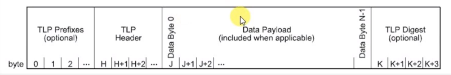
FIG: TLP Packet Format.
The Transaction Layer Packet Format is defined as:
事务层数据包格式定义如下:
-
Starts with a Prefix, which is an optional one and,
以一个可选的前缀开始, -
TLP Header and then,
然后是 TLP 头部, -
With/Without Data Payload,
接着是数据载荷(可选), -
At the end of TLP Packet a TLP Digest,
在 TLP 数据包的末尾是一个 TLP 摘要, -
The information in TLP Packet Format is distributed as:
TLP 数据包格式中的信息分布如下:-
TLP Prefixes.
TLP 前缀 -
Header (mandatory).
头部(必选) -
Data (included when applicable): depends on the transaction type.
数据(根据事务类型决定是否包含)。 -
TLP Digest (optional).
TLP 摘要(可选)
-
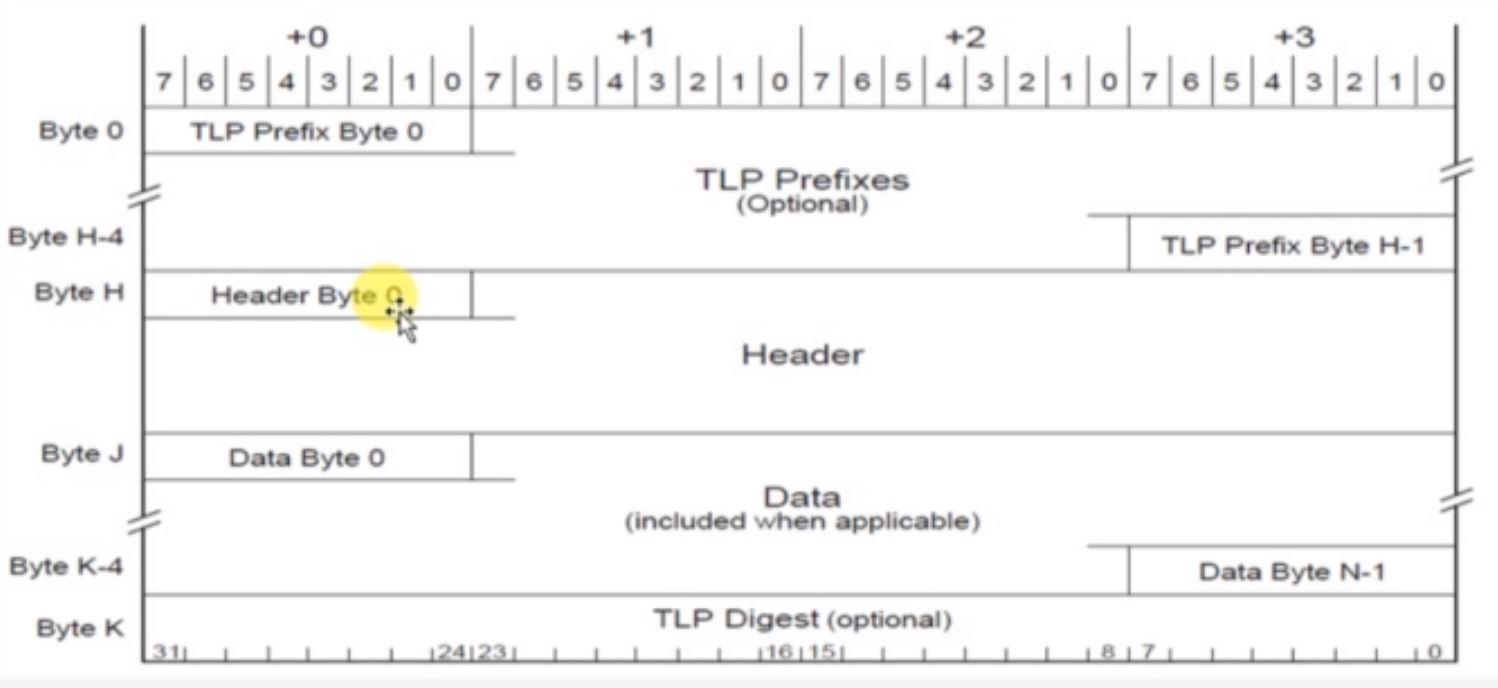
FIG: TLP Byte Information
TLP Header:
TLP 头部:
-
Provides Format of the packet.
提供数据包的格式。 -
Type of the packet.
数据包的类型。 -
Length of associated data, if available.
如果存在,提供相关数据的长度。 -
Transaction Descriptor.
事务描述符。 -
Address/Routing information
地址/路由信息 -
Byte enables
字节使能 -
Message encoding
消息编码 -
Completion Status
完成状态
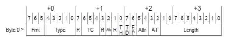
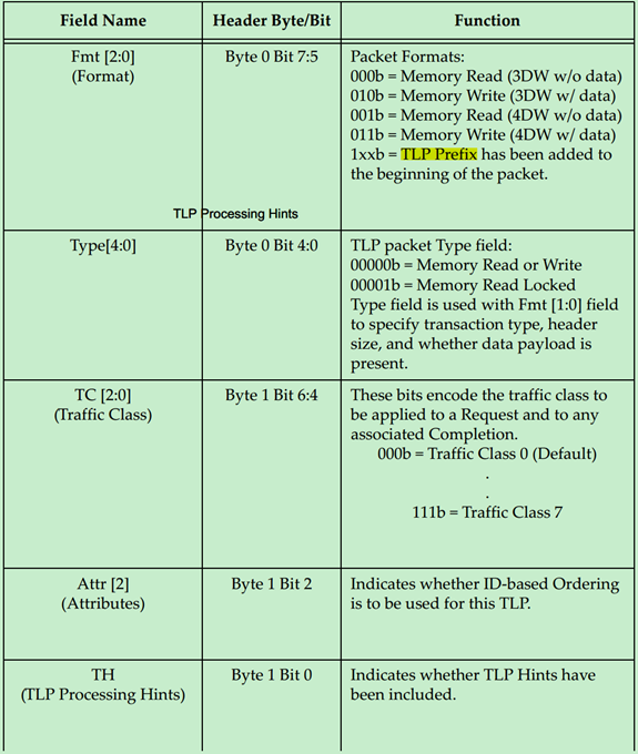
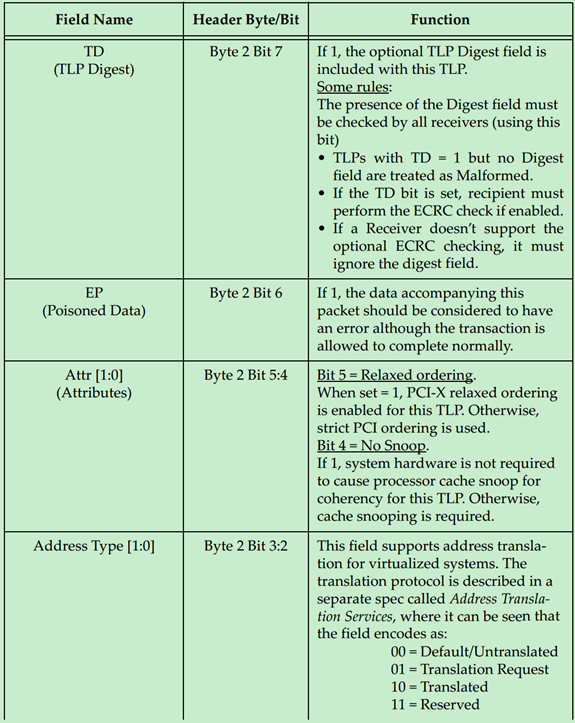
FIG: Common TLP Header.
-
32-bit if information.
32 位信息字段 -
Provides:
提供以下信息:- Format.
格式 - TLP Packet Type.
TLP 数据包类型 - Traffic Class info.
流量类别信息 - Attributes.
属性 - T Heads (Presence of TLP Prefix, if present).
T 头(如果存在 TLP 前缀) - TLP Digest.
TLP 摘要 - End Point (TLP is Normal or Poisoned).
端点(TLP 是正常还是被污染的) - Address Translation (When memory is available).
地址转换(当内存可用时) - Length (Data Length notation denoted in 32bit words).
长度(以 32 位字表示的数据长度)
- Format.
-
Fmt and Type define the Length of a Packet.
格式和类型定义了数据包的长度
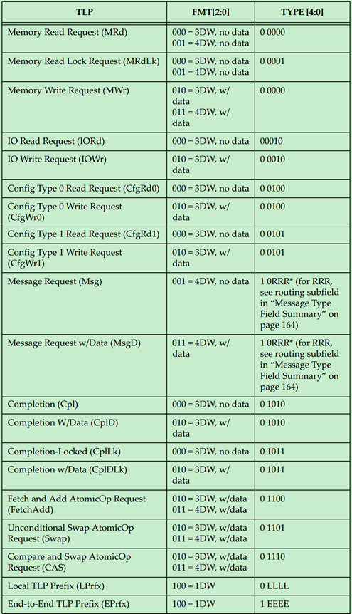
Packet format & Type Encoding:
数据包格式和类型编码:
| TLP Type TLP 类型 | Format 格式 | Type 类型 | Description 描述 |
|---|---|---|---|
| MR | 000 / 001 | 0 0000 | Memory Read Request 内存读取请求 |
| MRL | 000 / 001 | 0 0001 | Memory Read Request Locked 锁定的内存读取请求 |
| MW | 010 | 0 0000 | Memory Write Request 内存写入请求 |
| IOR | 000 | 0 0010 | I / O Read Request I/O 读取请求 |
| IOW | 010 | 0 0010 | I / O Write Request I/O 写入请求 |
| CR0 | 000 | 0 0100 | Configuration Read Type 0 配置读取类型 0 |
| CW0 | 010 | 0 0100 | Configuration Write Type 0 配置写入类型 0 |
| CR1 | 000 | 0 0101 | Configuration Read Type 1 配置读取类型 1 |
| CW1 | 010 | 0 0101 | Configuration Write Type 1 配置写入类型 1 |
| Msg | 001 | 1 0 r2 r1 r0 | Message Request 消息请求 |
| MsgD | 011 | 1 0 r2 r1 r0 | Message Request with Data 带数据的消息请求 |
Some additional Transaction types are as follows:-
一些额外的事务类型如下:
| TLP Type TLP 类型 | Format 格式 | Type 类型 | Description 描述 |
|---|---|---|---|
| Cpl | 000 | 0 1010 | Completion without data (0 Bytes) 不带数据的完成(0 字节) |
| CplD | 010 | 0 1010 | Completion with data (data will be present in TLP) 带数据的完成(数据将包含在 TLP 中) |
| CplLk | 000 | 0 1011 | Completion for Locked Memory read without data 锁定内存读取的完成(不带数据) |
| CplDLk | 010 | 0 1011 | Completion for Locked Memory Read 锁定内存读取的完成 |
| FetchAdd | 010 / 011 | 0 1100 | Fetch and Add atomic Operation Request 取并加原子操作请求 |
| Swap | 010 / 011 | 0 1101 | Unconditional Swap Atomic Operation Request 无条件交换原子操作请求 |
| CAS (Compare and Swap) | 010 / 011 | 0 1110 | Compare and swap Atomic Operation 比较并交换原子操作 |
| LPrfx | 100 | 0 L3 L2 L1 L0 | Local TLP Prefix 本地 TLP 前缀 |
| EPrfx | 100 | 1 E3 E2 E1 E0 | End-End TLP Prefix 端到端 TLP 前缀 |
TLP Length Encoding:
TLP 长度编码:
| Length [9:0] 长度 [9:0] | TLP Data Payload Size TLP 数据载荷大小 |
|---|---|
| 00 0000 0001 | 1 DW |
| 00 0000 0010 | 2 DW |
| … | |
| 11 1111 1111 | 1023 DW |
| 00 0000 0000 | 1024 DW |
-
DW: D Words.
DW:双字 -
All 1s: 1023 D Words.
全部为 1:1023 个双字 -
All 0s: 1024 D Words are present in the packet.
全部为 0:数据包中有 1024 个双字 -
Suppose there are 1024 D Words of data, then the Root Complex will divide the data into smaller packets and send them to the EndPoints. If there is a Switch present in between, then the data is forwarded as it is without splitting it into the packets or without any change.
假设数据有 1024 个双字,那么根复合体会将数据分成更小的数据包并发送到端点。如果中间有一个交换机,则数据将按原样转发,不会将其拆分成数据包或进行任何更改。
Address Formats:
地址格式:
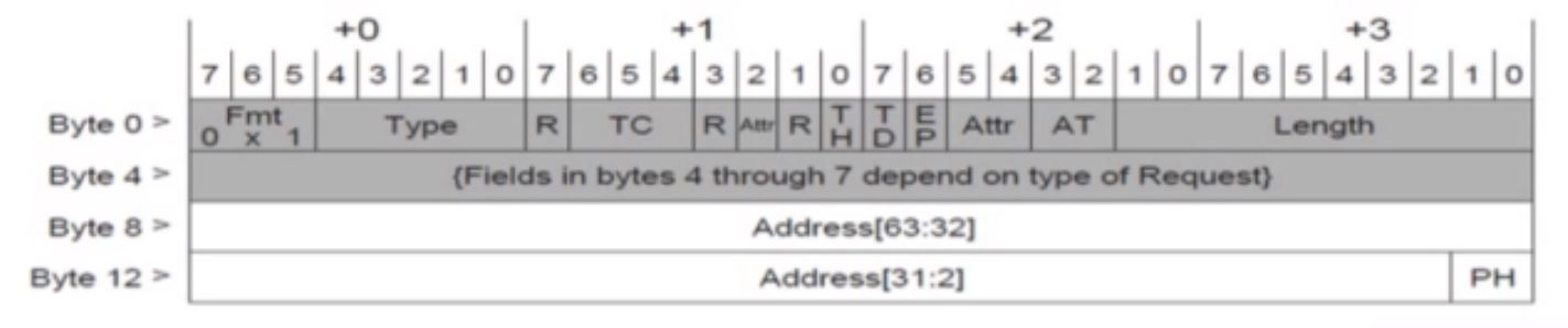
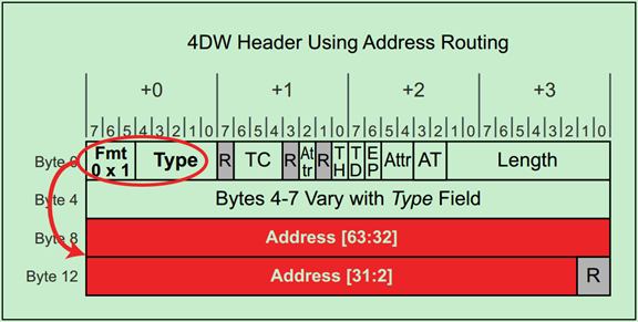
FIG: 64-bit Address Routing
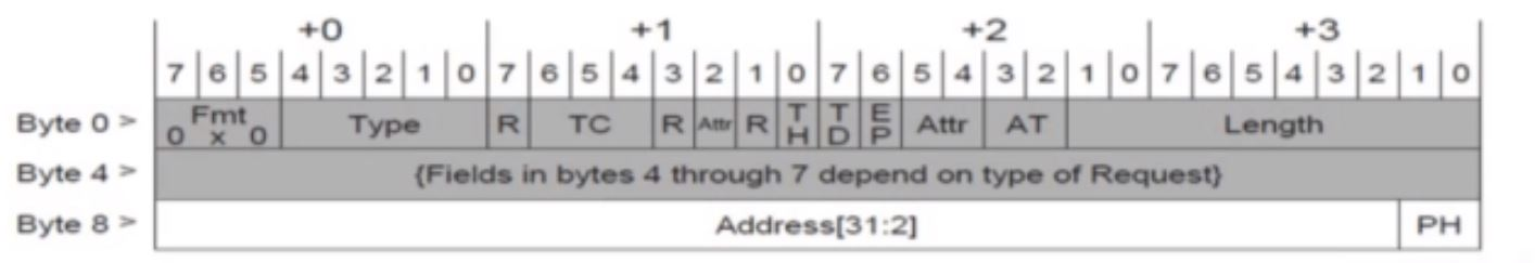
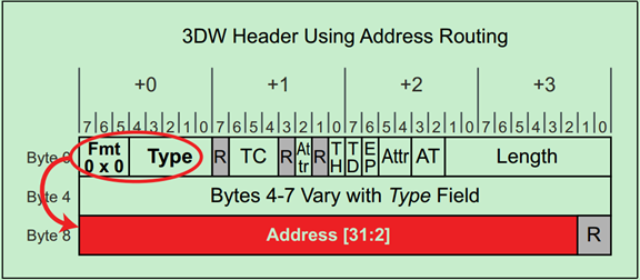
FIG: 32-bit Address Routing
Address Translation:
地址翻译:
| AT Coding 地址编码 | Description 描述 |
|---|---|
| 00 | Default / Untranslated 默认 / 未翻译 |
| 01 | Translation Request 翻译请求 |
| 10 | Translated 已翻译 |
| 11 | Reserved 保留 |
Routing:
路由:
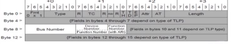
FIG: ID Routing with 4 DW Header
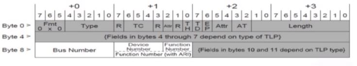
FIG: ID Routing with 3 DW Header
-
Data uses Routing information like, Bus Number; Device Number, Function Number, etc to reach a particular endpoint.
数据使用路由信息,如总线号、设备号、功能号等,到达特定的端点。 -
The Routing type (3 or 4 D Words of Header) depends on the need of TLP digest.
路由类型(3 或 4 个双字的头部)取决于 TLP 摘要的需求。 -
The Switch checks for Bus Number and Device Number and it forwards the packet to that particular endpoint accordingly in order to perform the Routing during the Run-Time.
交换机会检查总线号和设备号,并将数据包相应地转发到特定的端点,以在运行时执行路由。
PCIe Configuration Space:
PCIe 配置空间:
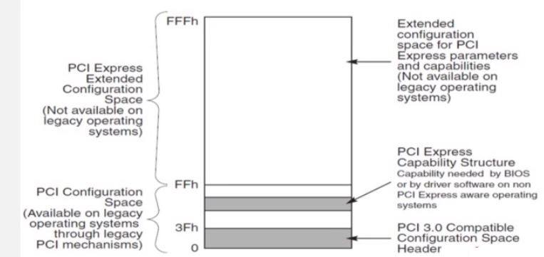
FIG: Configuration Space.
-
4KB of Space.
4KB 的空间 -
Starts from 0 to fff.
从 0 到 fff 开始 -
0 to 255 (256B) of PCIe Config Space.
从 0 到 255(256 字节)的 PCIe 配置空间 -
from 100 to fff of Extended PCIe Configuration Space.
从 100 到 fff 的扩展 PCIe 配置空间 -
While defining legacy PCI compatible mode and O.S., this kind of (0-fff) space is not available.
在定义传统 PCI 兼容模式和操作系统时,这种(0-fff)空间是不可用的 -
0-3f is PCIe Compatibility Configuration Space.
0-3f 是 PCIe 兼容配置空间 -
PCIe Capability Structure determines if Extended Configuration space for PCI is present or not.
PCIe 功能结构决定了是否存在 PCI 的扩展配置空间 -
0-ff PCI Configuration Space is analogous to PCIe-PCI and it has different kinds of information.
0-ff 的 PCI 配置空间类似于 PCIe-PCI,并且包含不同类型的信息 -
Configuration Space can be either of Type-0 or Type-1.
配置空间可以是 Type-0 或 Type-1
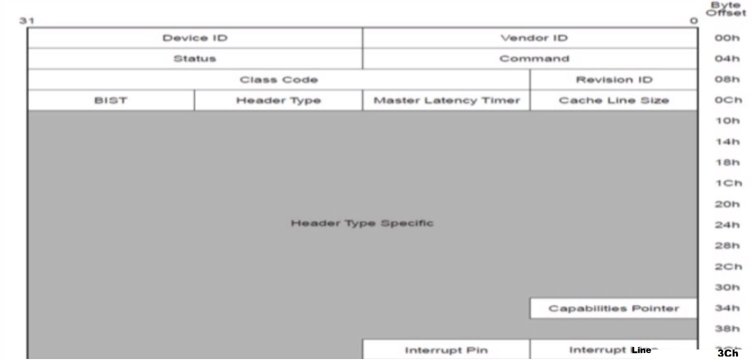
FIG: Type 0 / 1 Configuration Space
-
Type 0: Used for Endpoints.
Type 0:用于端点。 -
Type 1: Used for Switches and Root Complex.
Type 1:用于交换机和根复合体。 -
Common information provided for both type 0/1 is shown above.
上面显示了 Type 0 和 Type 1 的共同信息。 -
Identification Registers:
识别寄存器: -
Device ID:
设备 ID: -
Device unique identification value.
设备的唯一识别值。 -
Vendor ID:
厂商 ID: -
Vendor unique identification value.
厂商的唯一识别值。
PCIe ConfigSpace Command Register:
PCIe 配置空间命令寄存器:
| Bit 位 | Register 寄存器 | Description 描述 |
|---|---|---|
| 2 | Bus Master Enable 总线主控使能 | Controls the PCIe Endpoint to issue memory / IO request 控制 PCIe 端点发出内存 / I/O 请求 |
| 3 | Special Cycle Enable 特殊周期使能 | Not applicable to PCIe 对 PCIe 不适用 |
| 4 | Memory Write and Invalidate 内存写入并使无效 | N/A to PCIe 对 PCIe 不适用 |
| 5 | VGA Palette Snoop VGA 调色板窥探 | N/A to PCIe 对 PCIe 不适用 |
| 6 | Parity Error Response 奇偶校验错误响应 | Logging of Master Data Parity error 记录主数据奇偶校验错误 |
| 7 | IDSEL IDSEL | N/A to PCIe 对 PCIe 不适用 |
| 8 | SERR# (S error) Enable SERR# (S 错误) 使能 | Enables reporting of non-fatal & fatal error 启用非致命和致命错误的报告 |
| 9 | Fast back-to-back transaction enable 快速背靠背事务使能 | N/A to PCIe 对 PCIe 不适用 |
| 10 | Interrupt Disable 中断禁用 | Controls the ability of PCIe function generate interrupts to Root Complex 控制 PCIe 功能向根复合体生成中断的能力 |
Status Register:
状态寄存器:
| Bit 位 | Register 寄存器 | Description 描述 |
|---|---|---|
| 3 | Interrupt Status 中断状态 | Set indicates INTx emulation interrupt is pending or if it has been processed by the CPU or Root Complex 设置表示 INTx 模拟中断正在等待处理,或者已被 CPU 或根复合体处理 |
| 4 | Capabilities List 功能列表 | Indicates presence of Extended PCIe capability list 表示存在扩展 PCIe 功能列表 |
| 5 | 66MHz 66MHz | N/A to PCIe 对 PCIe 不适用 |
| 7 | Fast back-to-back enable 快速背靠背使能 | N/A to PCIe 对 PCIe 不适用 |
| 8 | Master Data Parity Error 主数据奇偶校验错误 | Set by endpoint if parity error response bit in Command Register received by the endpoint 如果端点收到的命令寄存器中的奇偶校验错误响应位被设置,则由端点设置 |
| 10:9 | DEVSEL (Device Select) timing DEVSEL (设备选择) 定时 | N/A to PCIe 对 PCIe 不适用 |
| 11 | Signaled Target Abort 已发出目标中止 | Set when a function completes as a Completor Abort Error 当一个功能作为完成者中止错误完成时设置 |
| 12 | Received Target Abort 已接收目标中止 | Set when function receives completion with abort 当功能接收到带有中止的完成时设置 |
| 13 | Received Master Abort 已接收主中止 | Set when requester receives a completion with unsupported request completion status 当请求者接收到带有不支持的请求完成状态的完成时设置 |
| 14 | Signaled System Error 已发出系统错误 | Set when the function sends a fatal or non-fatal error message 当功能发送致命或非致命错误消息时设置 |
| 15 | Detected Parity Error 已检测到奇偶校验错误 | Set when function receives poisoned TLPs 当功能接收到被污染的 TLP 时设置 |
Registers:
寄存器:
-
Cache Line Register
缓存行寄存器 -
Latency Timer Register
延迟计时器寄存器 -
Interrupt Line Register
中断线寄存器 -
Interrupt Pin Register
中断引脚寄存器 -
Error Register
错误寄存器
PCI Type-0 Configuration Space:
PCI Type-0 配置空间:
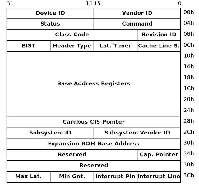
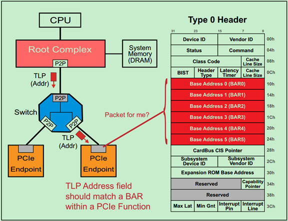
FIG: Type 0 PCI Configuration Space
-
BAR (Base Address Registers) space is used to map the internal functions or internal memory requests into the corresponding system memory.
基地址寄存器(BAR)空间用于将内部功能或内部内存请求映射到相应的系统内存。 -
To summarize, Base Address Registers or BAR (offset 10h - 24h)
总之,基地址寄存器或 BAR(偏移量 10h - 24h): -
Resources are mapped into memory space using BAR registers.
使用 BAR 寄存器将资源映射到内存空间。 -
Supports 64bit addressing for any BAR request prefetchable memory.
支持任何 BAR 请求的 64 位可预取内存地址。 -
Minimum memory space range requested is 128 Bytes. Whenever we are Writing into that BAR Register and Read Back the information, whatever size it supports will be set to 1 and others to 0. With this, we can come to a conclusion of BAR base address 0 and if it needs to be allocated or not (BAR = 0 implies Not in Use).
请求的最小内存空间范围是 128 字节。当我们写入该 BAR 寄存器并读回信息时,它支持的大小将被设置为 1,其他为 0。通过这种方式,我们可以得出 BAR 基地址 0 是否需要分配的结论(BAR = 0 表示未使用)。 -
Minimum Grant / Maximum Latency Registers (offset 3Eh / 3Fh)
最小授权 / 最大延迟寄存器(偏移量 3Eh / 3Fh) -
N/A to PCIe, Hardwired to 00h.
对 PCIe 不适用,硬连线为 00h。
PCI Type-1 Configuration Space:
PCI Type-1 配置空间:
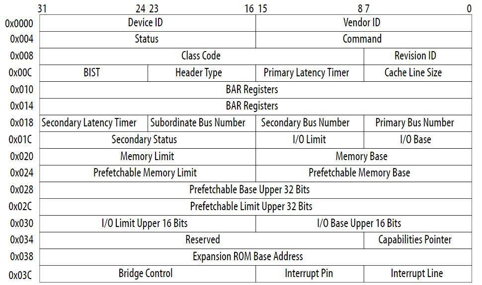
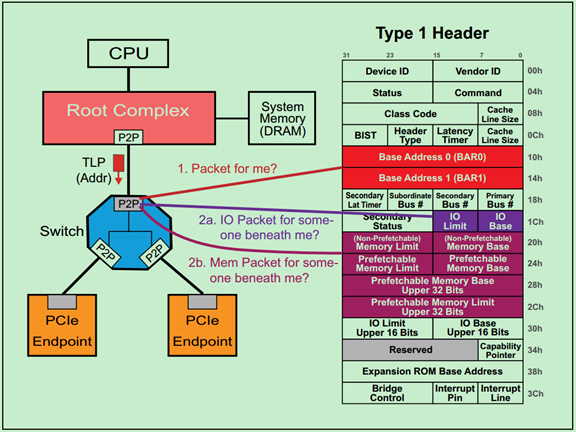
FIG: Type 1 PCI Configuration Space
Registers:
寄存器:
-
Base Address Register (offset 10h / 14h)
基地址寄存器(偏移量 10h / 14h) -
Primary Bus Number (Root Complex - 0)
主总线号(根复合体 - 0) -
Secondary Bus Number (Enumerated during the runtime)
次级总线号(在运行时枚举) -
Secondary Latency Timer (N/A for PCIe)
次级延迟计时器(对 PCIe 不适用) -
Secondary Status Register (similar to Common Status Register)
次级状态寄存器(类似于通用状态寄存器) -
Prefetchable Memory Base / Limit
可预取内存基址 / 限制 -
Bridge Control Register (used for bridging PCIe to PCI)
桥接控制寄存器(用于将 PCIe 桥接到 PCI)
PCIe TLP 路由分为几类?都有什么作用
posted @ 2025-01-12 12:25 yooooooo
PCIe TLP(事务层数据包)路由主要分为以下几类及其作用:
1. 基于地址的路由 (Address-Based Routing)
- 作用:用于内存读写(Memory Read/Write)和输入/输出读写(I/O Read/Write)等事务。TLP 头部包含目标地址,交换机根据该地址将 TLP 转发至正确的设备。
2. 基于 ID 的路由 (ID-Based Routing)
- 作用:用于配置读写(Configuration Read/Write)和消息事务。TLP 头部包含目标设备的总线号(Bus)、设备号(Device)和功能号(Function),交换机根据这些信息转发 TLP。
3. 隐式路由 (Implicit Routing)
- 作用:用于特定消息事务,例如电源管理和错误处理。TLP 无需明确的目标地址或 ID,交换机根据 TLP 的类型将其转发至根复合体(Root Complex)或其他指定设备。
总结
- 基于地址的路由:处理内存和 I/O 事务。
- 基于 ID 的路由:处理配置和消息事务。
- 隐式路由:处理特定系统级消息。
这些路由机制确保 TLP 能够准确到达目标设备。
TLP 路由(Routing)基础
发表于 4/3/2018 8:17:03 PM
首先来分析一个例子,如下图所示:
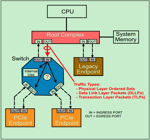
当包(Packet)到达 Switch 的输入端口(Ingress Port)时,端口首先会检查包是否有错误,然后根据包的路由(Routing)信息,来做出以下三种处理方式之一:
1、 接受这个包,并自己(Switch)使用它(Internal Use);
2、 将其通过响应的输出端口(Egress Port)转发到下一级 Endpoint(或者下一级 Switch);
3、 拒绝接受这个包。
在前面的文章中多次介绍过,PCIe 总线中一共有三种类型的包:Ordered Sets(命令集包,只在相邻的设备的物理层之间进行传递,不会被转发到其他的设备中)、DLLPs(数据链路层包,只在相邻的设备的数据链路层之间进行传递,不会被转发到其他设备中)和 TLPs(事务层包,可以根据包中的路由信息被转发到其他的设备中)。
注:
-
实际上不论是 TLPs 还是 DLLPs 都会经过物理层,这里说的 TLP 和 DLLP 指的是包的最初来源分别是事务层和数据链路层,即 DLLP 和上一层的事务层没有什么关系,其内容和作用完全是由数据链路层自己决定的。
-
Endpoint 不仅可以发送 TLP 给其上层的设备(如 Root),也可以发送 TLP 给其他的 Endpoint,当然这需要借助 Switch 来实现。这种传输方式叫做 Peer-to-Peer。
TLP 一共有三种路由方式,分别是 ID 路由(ID Routing,即 BDF Routing)、地址路由(Address Routing,包括 Memory 和 IO)以及模糊路由(Implicitly Routing)。本文将简单介绍一些关于 TLP 路由的基础知识,具体的路由方式将会在接下来的三篇文章中依次进行介绍。
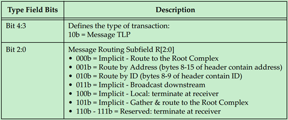
具体采用哪一种路由方式是由 TLP 的类型所决定的,如下表所示:
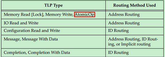
注:
-
AtomicOp 是 PCIe Spec V2.1 新增的内容,有兴趣的可以自行阅读 V2.1 的相关内容。
-
一般情况下,Message 都是使用模糊路由(Implicitly Routing)的,但是也有 PCIe 设备厂商自定义的 Message 会使用地址路由或者 ID 路由。
可能有的人要有疑惑了,既然 Message 可以使用地址路由或者 ID 路由,为什么还要单独搞出来一个模糊路由呢?原因很简单,使用模糊路由可以广播 Message 到每一个设备,采用其他的路由方式必须明确指定是哪一个设备。
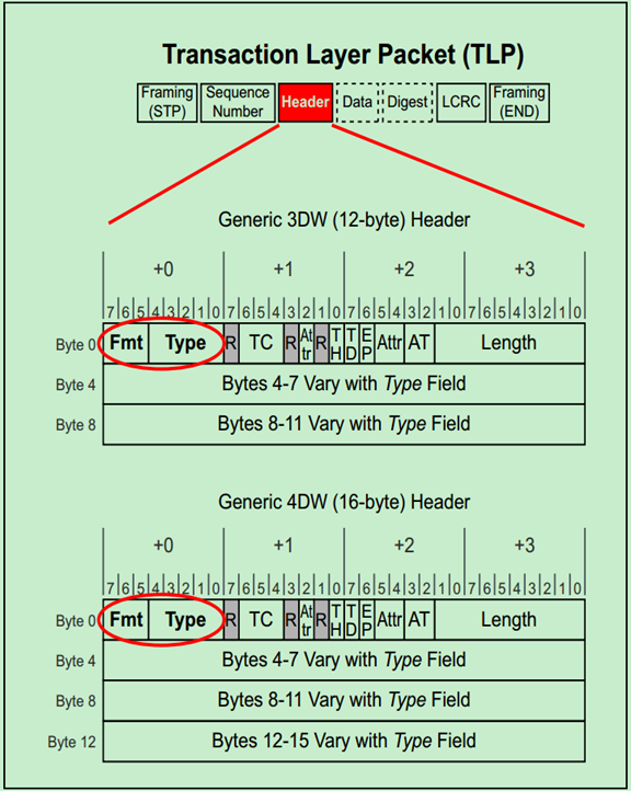
那么 PCIe 中是如何来判断 TLP 的类型的呢?又是如何判断其为 Request 还是 Completion 的呢?实际上是通过 TLP Header 的 Format 和 Type 部分来确定的,如下图所示:
TLP 路由之 ID Routing
发表于 4/3/2018 8:18:21 PM
ID 路由(ID Routing)有的时候也被称为 BDF 路由,即采用 Bus Number、Device Number 和 Function Number 来确定目标设备的位置。这是一种兼容 PCI 和 PCI-X 总线协议的路由方式,主要用于配置请求(Configuration Request)的路由,在 PCIe 总线中,其还可以被用于 Completion 和 Message 的路由。
前面的文章提到过,TLP 的 Header 有 3DW 的和 4DW 的,其中 4DW 的 Header 一般只用于 Message 中。使用 ID 路由的 TLP Header 以下两张图所示,第一个为 3DW Header,第二个为 4DW Header:
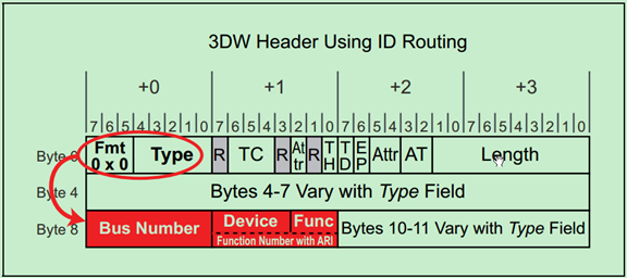
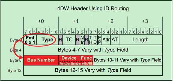
对于 Endpoint 来说,其只需要检查 TLP Header 中的 BDF 是否与自己的 BDF 一致,如果一致,则认为是发送给自己的,否则便会忽略该 TLP。
** 注:** 很多初学者可能都会有这样的一个疑问:采用 ID 路由的 TLP Header 中并未包含 Requester 的 ID(BDF),那么 Completer 怎么确定 Requester 的位置呢?实际上这个问题并不难回答,因为 ID 路由主要用于配置请求和 Completion,偶尔也用于一些厂商自定义的 Message。首先,配置请求的 Requester 只能是 Root,所以不需要确定其位置;再之,Completion 用于对其他路由方式的回应,如地址路由中包含了 Requester 的 BDF;最后,Message 是 Posted 型的,即其根本不需要 Completion,自然也就不需要 Requester 的 BDF 了。
** 注:** 实际上 PCIe 是一种点对点(Point-to-Point)的通信方式,即每个链路只能连接一个设备,因此大部分情况下使用 5bit 的空间来描述 Device Number 完全是多余的。为此,PCIe Spec 提出了 ARI 格式,这里暂时不详细介绍了,有兴趣的可以自行阅读 PCIe Spec 的相关内容。
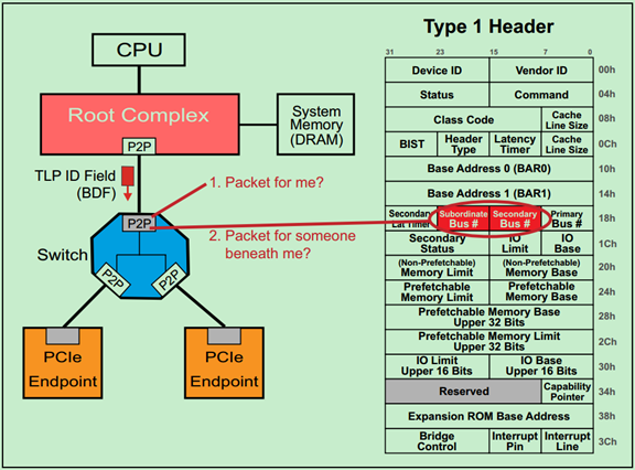
对于 Switch 来说,则需要根据 TLP Header 中的 BDF 来判断,这个 TLP 是给自己的还是给自己下属的其他设备的。如下图所示:
TLP 路由之 Address Routing
发表于 4/3/2018 8:19:56 PM
地址路由(Address Routing)的地址包括 IO 和 Memory。对于 Memory 请求来说,32bit 的地址使用 3DW 的 Header,64bit 的地址使用 4DW 的 Header。而 IO 请求则只能使用 32bit 的地址,即只能使用 3DW 的 Header。
** 注:** 再次强调,IO 请求是为了兼容早期的 PCI 设备的,在新的 PCIe 设备中禁止使用。
3DW 和 4DW 的 TLP Header 分别如以下两张图所示:
当 Endpoint 接收到采用地址路由的 TLP 时,其会根据该 TLP Header 中的地址信息和自己的配置空间中的 BAR 寄存器来判断这个 TLP 是不是自己的。如下图所示:
Switch 的地址路由机制如下图所示:
TLP 路由之 Implicit Routing
发表于 4/3/2018 8:20:57 PM
模糊路由(Implicit Routing,又译为隐式路由)只能用于 Message 的路由。前面的文章中多次提到过,PCIe 总线相对于 PCI 总线的一大改进便是消除了大量的边带信号,这正是通过 Message 的机制来实现的。
PCIE 中的带内(in-band)包和边带信号(side-band)
挣扎着的咸鱼于 2023-07-15 16:05:27 发布
1. 带内(in-band)包
带内包是指在 PCIE 协议中用于数据传输和控制的标准数据包。这些数据包是 PCIE 协议的核心组成部分,用于实现设备之间的通信。常见的带内包类型包括:
- Memory Read(MemRd):用于从内存中读取数据的请求包。
- Memory Write(MemWr):用于向内存写入数据的请求包。
- Message:用于传递特定控制信息或状态信号的数据包。
2. 边带信号(Side-band Signal)
边带信号是指在 PCIE 协议中不通过数据链路传输,而是通过独立的物理引脚进行传输的信号。这些信号通常用于实现一些特定的功能,例如中断请求。边带信号的主要特点包括:
- 它们是可选信号,不属于 PCIE 协议的强制性组成部分。
- 它们仅在特定的系统环境中使用,通常局限于处理器系统内部,无法在系统外部使用。
边带信号的定义
根据 PCI 规范,边带信号的定义如下:
任何不属于 PCI 规范定义的信号,但连接两个或多个 PCI 兼容设备,并且仅对这些设备具有特定意义的信号。
边带信号的实例
在 PCI 总线架构中,中断信号
INTA#、INTB#、INTC#和INTD#是典型的边带信号。这些信号用于向处理器发出中断请求,其电平为低电平有效,并与处理器的中断控制器直接相连。PCI 总线规范并未明确规定这些信号在处理器系统中的具体使用方式,因为它们属于可选信号。

PCIe 定义的 Message 主要有以下几种类型:
・Power Management
・INTx legacy interrupt signaling
・Error signaling
・Locked Transaction support
・Hot Plug signaling
・Vendor‐specific signaling
・Slot Power Limit settings
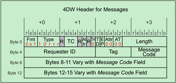
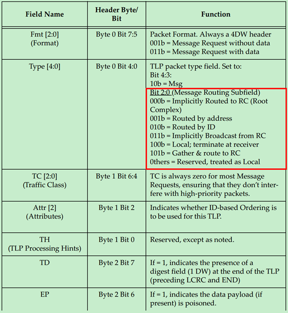
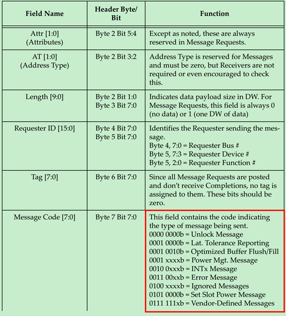
所有采用模糊路由的 TLP 的 Header 都是 4DW 的,具体如下图所示:
其中 Type 决定了模糊路由的类型,具体如下图所示:
TLP Header 详解(一)
发表于 4/6/2018 10:15:56 AM
事务层包(TLP)的一般格式如下图所示:
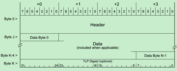
前面的文章介绍过,TLP Header 为 3DW 或者 4DW,Data Payload 为 1-1024DW,最后的 TLP Digest(ECRC)是可选的,为 1DW。
TLP Header 在整个 TLP 的位置如下图所示,需要注意的是,TLP Header 的格式和内容都会随着 TLP 的类型和路由方式的改变而改变。
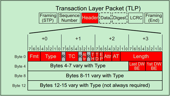
TLP 的类型和路由方式由 Fmt 和 Type 所决定,这在前面关于 TLP 路由的文章中已经详细的介绍过。上图显示的是各种不同格式的 TLP Header 的相同的部分。
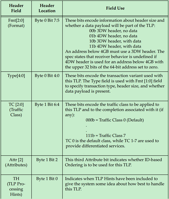
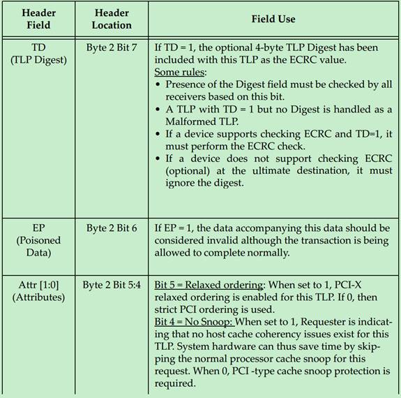
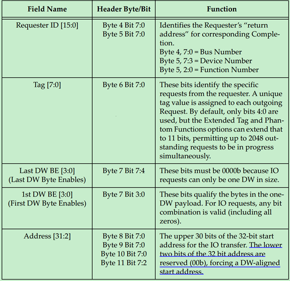
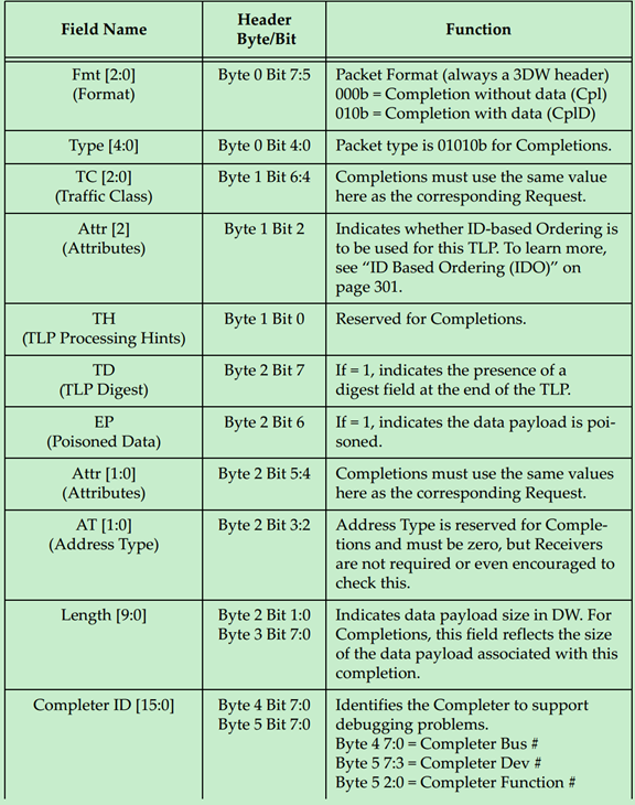
每一个 Field 的作用与意义如下表所示:
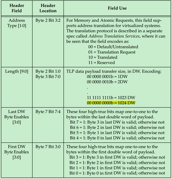
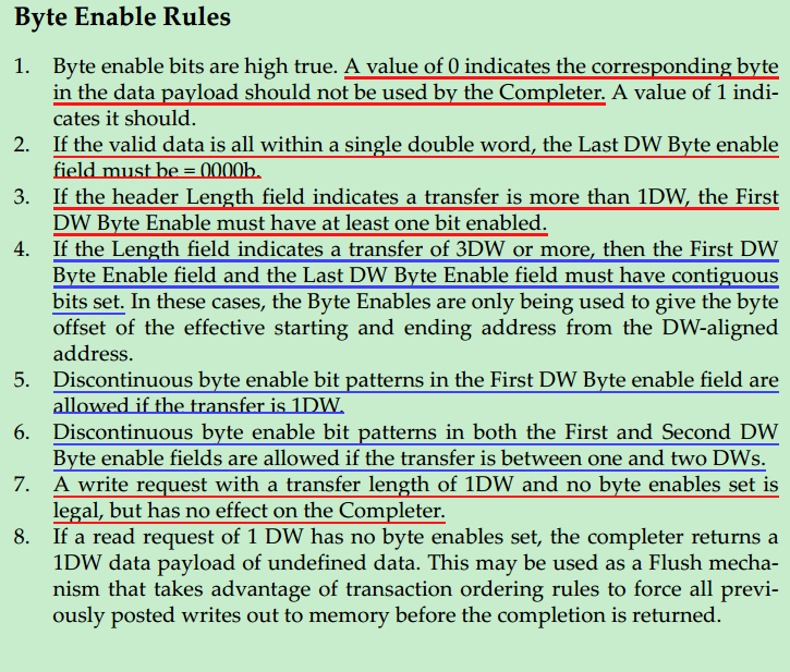
下面分别详细地介绍一下 Byte Enable,在 PCIe 中 Data Payload 的单位是 DW,也就是说数据大小(地址)需要以 DW 作为对齐。但是很多情况下,数据的大小并不是 DW 的整数倍,因此 PCIe 引入了 Byte Enable 来解决这一问题。使用 Byte Enable 需要遵循一下原则:
・Byte Enable 为高电平有效,低电平(0)表示 Data Payload 的对应 Byte 将被认为是无效的,即不被 Completer 使用。
・如果有效数据小于 1DW,则 Last DW Byte Enable 应全部为 0。
・如果 Data Payload 大于 1DW,则 First DW Byte Enable 至少有一位是有效的。
・如果 Data Payload 大于或等于 3DW,则 First DW Byte Enable 和 Last DW Byte Enable 当中的有效位必须是连续的。即这种情况下,Byte Enable 只能用于调整起始地址和结束地址。
・如果 Data Payload 等于 1DW,则 First DW Byte Enable 中的有效位可以是不连续的。
・如果 Data Payload 等于 2DW,则 First DW Byte Enable 和 Last DW Byte Enable 中的有效位都可以是不连续的。
・写请求中的 DW 等于 1,但是 First DW Byte Enable 中没有任何一位是有效的,也是允许的,但是这样的请求对于 Completer 没有任何作用。
・如果读请求 DW 等于 1,但是 First DW Byte Enable 中没有任何一位是有效的,此时 Completer 会返回 1DW 的 Data Payload,只是其中的数据都是无效的。这一方式常备用于 Flush Mechanism。
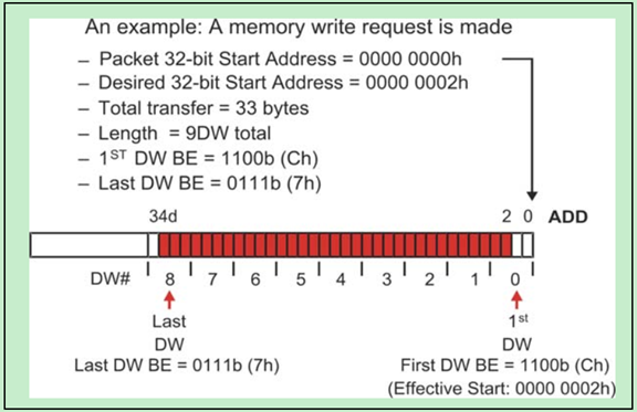
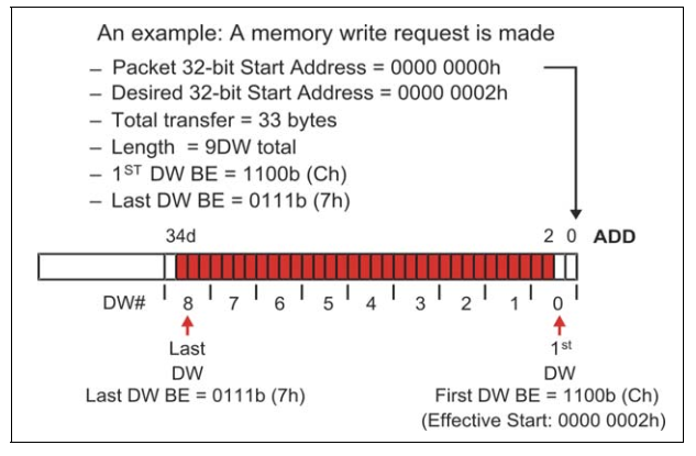
一个简单的 Byte Enable 使用的例子,如下图所示:
关于 TLP 的 Data Payload 有:
・Data Payload 的大小由 TLP Header 中的 Length 决定。
・Data Payload 的数据采用的是 Little Endian,即低字节存放于低地址中。
・Data Payload 的大小并不是有效的数据的大小,有效数据的大小是由 Data Payload 和 Byte Enable 共同决定的。
・当 TLP 类型为 Message 时,Length 一般是保留的(Reserved),除非该 Message 是带有数据的(MsgD)。
・TLP 的 Data Payload 大小不得超过 Max_Payload_Size 的值,该值位于 Device Control Register 中。对于比较大的数据量,因此只能分多次进行发送。对于读请求来说,并没有 Data Payload,也就是说该规则并不适用于读请求。
・需要特别注意的是,起始地址和结束地址之间不能够跨越 4KB 的地址边界。
TLP Header 详解(二)
发表于 4/6/2018 10:19:17 AM
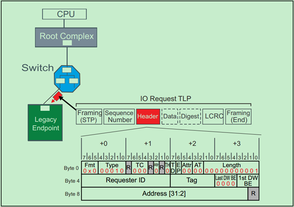
下面用几个具体的例子来讲解 TLP Header 的格式与作用。因为内容较多,所以分为多篇文章分别进行介绍。第一篇(即本文)介绍 IO Request、Memory Request 和 Configuration Request。第二篇文章(即 TLP Header 详解三)介绍 Completion ,第三篇文章(即 TLP Header 详解四)介绍 Message Request。
IO Request
IO Request 的 TLP Header 的格式如下图所示:
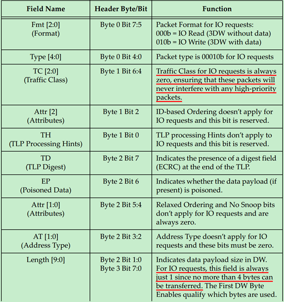
Memory Request
Memory Request 的 TLP Header 的格式如下图所示:
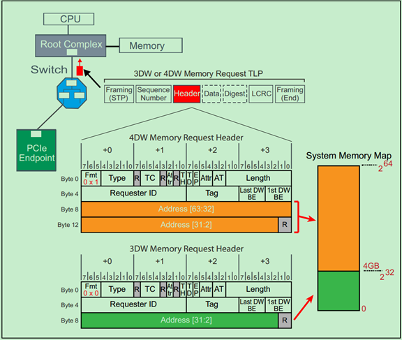
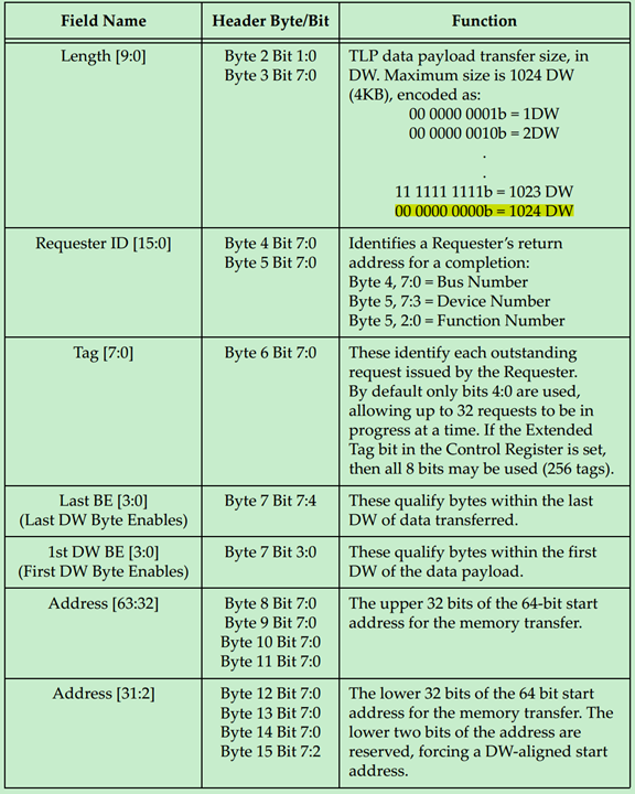
** 注:**TLP Prefix、ID Based Ordering(IDO)和 TLP Processing Hints(TH)均为 PCIe Spec V2.1 提出的。
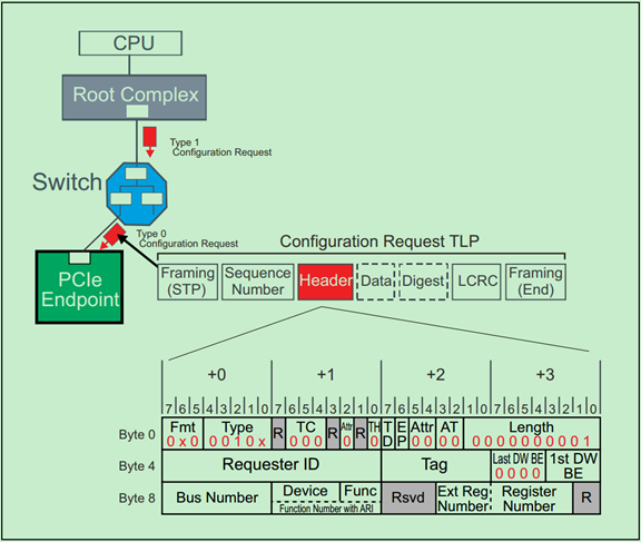
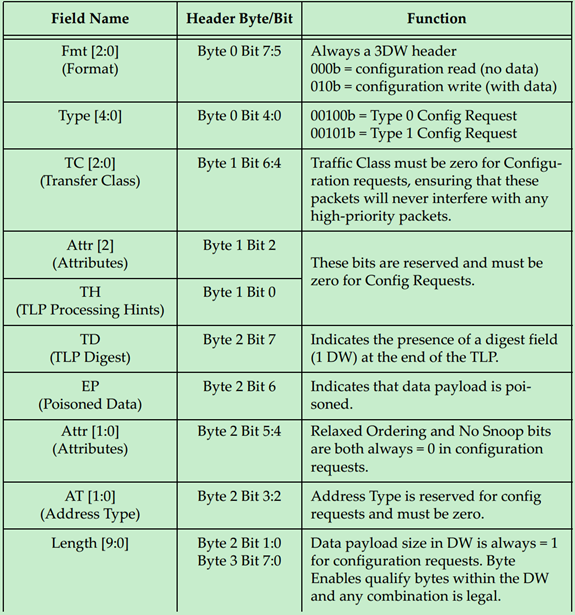
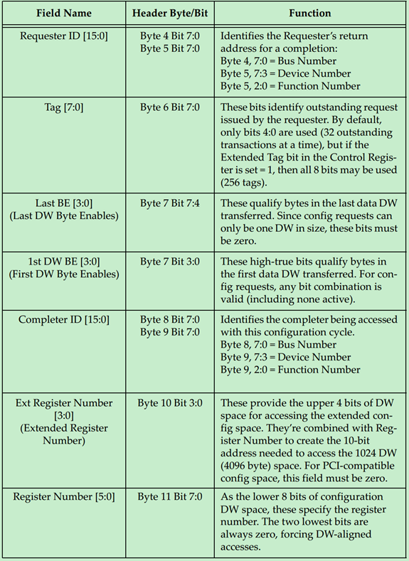
Configuration Request
Configuration Request 的 TLP Header 的格式如下图所示:
** 补充说明:关于 Byte Enable 的规则和一个简单的例子如下:**
 **
**
**
TLP Header 详解(三)
发表于 4/6/2018 10:20:44 AM
Completions
Completions 的 TLP Header 的格式如下图所示:
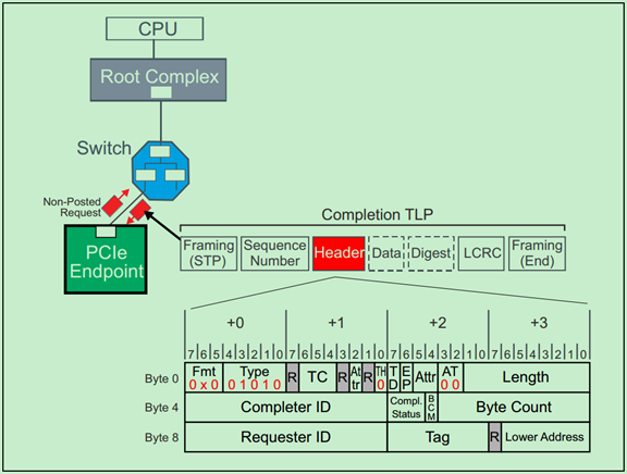
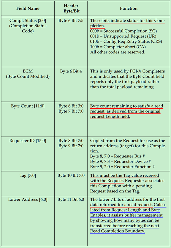
这里来解释一下 Completion Status Codes
・000b (SC) Successful Completion:表示请求(Request)被正确的处理;
・001b (UR) Unsupported Request:表示请求是非法的或者不能被 Completer 所识别的。在 PCIe V1.1 以及之后的版本将这作为 Advisory Non-Fatal Error;
・010b (CRS) Configuration Request Retry Status:Completer 暂时不能响应的配置请求,需要 Requester 稍后再次尝试;
・100b (CA) Completer Abort:Completer 可以响应该请求,但是却发生了其他的错误,该错误是 Uncorrectable Error。
关于 CplD,需要注意的是:
・前面的文章中多次提到,一个读请求可能会对应多个 CplD(因为 4KB 的地址边界问题,以及 RCB 的限制),但是返回的总的数据量应当与请求的数据量保持一致,否则可能会出现 Completion Timeout 的错误;
・一个 Completion 只能对应于一个 Request;
・IO 和 Configuration 读请求由于一直都是 1DW,因此其一直都只对应一个 Completion;
・当 Completion 中的状态码(Status Codes)为 SC(Successful)之外的状态,则一次传输(事务,Transaction)被终止;
・在处理一个请求多个 CplD 时,应当注意 Read Completion Boundary(RCB),RCB 的值可以是 64Bytes 或者 128Bytes;
・Bridge 和 Endpoint 应设计为 RCB 的大小是可以通过软件修改或控制的;
・在处理一个请求多个 CplD 时,应注意先发送的时低地址的数据,后发送高地址数据。
Requester 接受到 Completion 的处理规则:
・如果 Requester 接收到的 Completion 与自己之前发送的 Request 不一致,则会报错;
・当 Completion 中的状态码不是 SC 或者 CRS 的话,则会报错,并且相关的 Buff 都会被清空;
・当任何非配置请求的 Completion 中的状态码为 CRS 时,都会被认为是非法的,并被认为是 Malformed TLP;
TLP Header 详解(四)
发表于 4/16/2018 8:32:53 PM
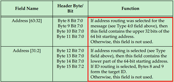
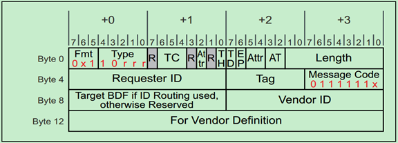
PCIe 中的 Message 主要是为了替代 PCI 中采用边带信号,这些边带信号的主要功能是中断,错误报告和电源管理等。所有的 Message 请求采用的都是 4DW 的 TLP Header,但是并不是所有的空间都被利用上了,例如有的 Message 就没有使用 Byte8 到 Byte15 的空间。
Message 请求的 TLP Header 格式如下图所示:
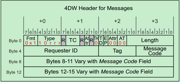
上面的表格中提到了,Message 主要有九个类型:
- INTx Interrupt Signaling
- Power Management
- Error Signaling
- Locked Transaction Support
- Slot Power Limit Support
- Vendor‐Defined Messages
- Ignored Messages (related to Hot‐Plug support in spec revision 1.1)
- Latency Tolerance Reporting (LTR)
- Optimized Buffer Flush and Fill (OBFF)
下面将分别进行介绍一下,
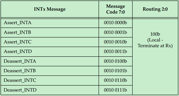
INTx Interrupt Messages
中断消息
PCI 2.3 提出了 MSI(Message Signaled Interrupt),但是早期的 PCI 并不支持这一功能,PCIe 为此定义了一种 Virtual Wire 来模拟 PCI 的中断引脚(INTA-INTD)。如下图所示:
INTx Message 的使用规则如下:
・They have no data payload and so the Length field is reserved.
・They’re only issued by Upstream Ports. Checking this rule for received packets is optional but, if checked, violations will be handled as Malformed TLPs.
・They are required to use the default traffic class TC0. Receivers must check for this and violations will be handled as Malformed TLPs.
・Components at both ends of the Link must track the current state of the four virtual interrupts. If the logical state of one interrupt changes at the Upstream Port, it must send the appropriate INTx message.
・INTx signaling is disabled when the Interrupt Disable bit of the Command Register is set = 1 (as would be the case for physical interrupt lines).
・If any virtual INTx signals are active when the Interrupt Disable bit is set in the device, the Upstream Port must send corresponding Deassert_INTx messages.
・Switches must track the state of the four INTx signals independently for each Downstream Port and combine the states for the Upstream Port.
・The Root Complex must track the state of the four INTx lines independently and convert them into system interrupts in an implementation‐specific way.
・They use the routing type “Local‐Terminate at Receiver” to allow a Switch to remap the designated interrupt pin when. Consequently, the Requester ID in an INTx message may be assigned by the last transmitter.
Power Management Messages
电源管理消息
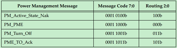
Power Management Messages 使用规则如下:
・Power Management Messages don’t have a data payload, so the Length field is reserved.
・They are required to use the default traffic class TC0. Receivers must check for this and handle violations as Malformed TLPs.
・PM_Active_State_Nak is sent from a Downstream Port after it observes a request from the Link neighbor to change the Link power state to L1 but it has chosen not to do so (Local ‐ Terminate at Receiver routing).
・PM_PME is sent upstream by the component requesting a Power Management Event (Implicitly Routed to the Root Complex).
・PM_Turn_Off is sent downstream to all endpoints (Implicitly Broadcast from the Root Complex routing).
・PME_TO_Ack is sent upstream by endpoints. For switches with multiple Downstream Ports, this message won’t be forwarded upstream until all Downstream Ports have received it (Gather and Route to the Root Complex routing).
Error Messages (错误消息)
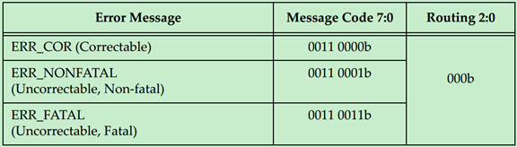
Error Message 使用规则如下:
・They are required to use the default traffic class TC0. Receivers must check for this and handle violations as Malformed TLPs.
・They don’t have a data payload, so the Length field is reserved.
・The Root Complex converts Error Messages into system‐specific events.
Locked Transaction Support
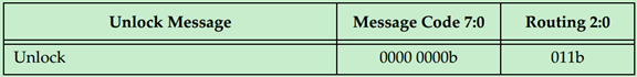
Unlock Message 使用规则:
・They are required to use the default traffic class TC0. Receivers must check for this and handle violations as Malformed TLPs.
・They don’t have a data payload, and the Length field is reserved.
Set Slot Power Limit Message
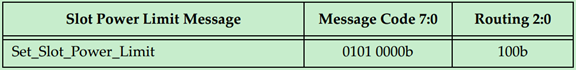
Set_Slot_Power_Limit Message 使用规则:
・They’re required to use the default traffic class TC0. Receivers must check for this and handle violations as Malformed TLPs.
・The data payload is 1 DW and so the Length field is set to one. Only the lower 10 bits of the 32‐bit data payload are used for slot power scaling; the upper payload bits must be set to zero.
・This message is sent automatically anytime the Data Link Layer transitions to DL_Up status or if a configuration write to the Slot Capabilities Register occurs while the Data Link Layer is already reporting DL_Up status.
・If the card in the slot already consumes less power than the power limit specified, it’s allowed to ignore the Message.
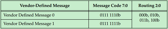
Vendor**‐Defined Message 0 and 1**
 v
v
厂商自定义 Message 使用规则:
・A data payload may or may not be included with either type.
・2. Messages are distinguished by the Vendor ID field.
・3. Attribute bits [2] and [1:0] are not reserved.
・4. If the Receiver doesn’t recognize the Message:
・Type 1 Messages are silently discarded
・Type 0 Messages are treated as an Unsupported Request error condition
Ignored Messages
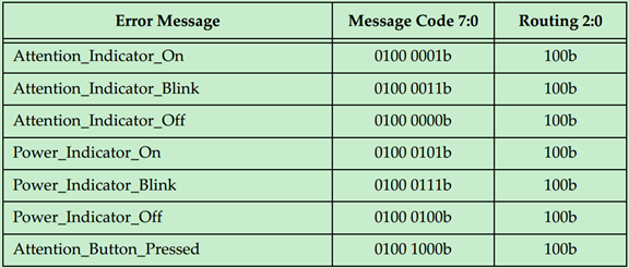
Hot Plug Message 使用规则:
・They are driven by a Downstream Port to the card in the slot.
・The Attention Button Message is driven upstream by a slot device.
Latency Tolerance Reporting Message
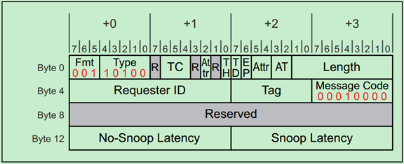
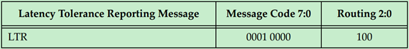
LTR Message 使用规则:
・They are required to use the default traffic class TC0. Receivers must check for this and handle violations as Malformed TLPs.
・They do not have a data payload, and the Length field is reserved.
Optimized Buffer Flush and Fill Messages
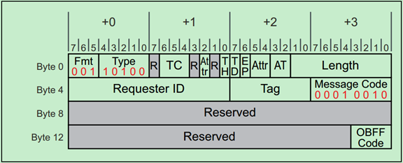
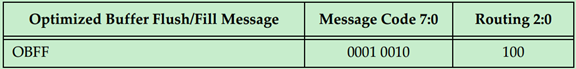
OBFF Message 使用规则:
・They are required to use the default traffic class TC0. Receivers must check for this and handle violations as Malformed TLPs.
・They do not have a data payload, and the Length field is reserved.
・The Requester ID must be set to the Transmitting Port’s ID.
via:
-
PCIe - TLP Header, Packet Formats, Address Translation, Config Space, Command Register, Configuration types
https://www.semisaga.com/2019/07/pcie-tlp-header-packet-formats-address.html- Transaction Layer Packet (TLP) Header Formats
https://www.intel.com/content/www/us/en/docs/programmable/683647/18-0/transaction-layer-packet-tlp-header-formats.html
- Transaction Layer Packet (TLP) Header Formats
-
PCIe TLP 路由分为几类?都有什么作用 - yooooooo - 博客园
https://www.cnblogs.com/linhaostudy/p/18666862 -
PCIe 扫盲 ——TLP 路由(Routing)基础 - Felix
https://blog.chinaaet.com/justlxy/p/5100053323 -
PCIe 扫盲 ——TLP 路由之 ID Routing-Felix
https://blog.chinaaet.com/justlxy/p/5100053324 -
PCIe 扫盲 ——TLP 路由之 Address Routing-Felix
https://blog.chinaaet.com/justlxy/p/5100053325 -
PCIe 扫盲 ——TLP 路由之 Implicit Routing-Felix
https://blog.chinaaet.com/justlxy/p/5100053326- PCIE 中的带内(in-band)包和边带信号(side-band)是啥?-CSDN博客
https://blog.csdn.net/m0_61703043/article/details/131740521
- PCIE 中的带内(in-band)包和边带信号(side-band)是啥?-CSDN博客
-
PCIe 扫盲 ——TLP Header 详解(一)-Felix
https://blog.chinaaet.com/justlxy/p/5100053352 -
PCIe 扫盲 ——TLP Header 详解(二)-Felix
https://blog.chinaaet.com/justlxy/p/5100053353 -
PCIe 扫盲 ——TLP Header 详解(三)-Felix
https://blog.chinaaet.com/justlxy/p/5100053354 -
PCIe 扫盲 ——TLP Header 详解(四)-Felix
https://blog.chinaaet.com/justlxy/p/5100053463