海口模板建站哪家好美国今天刚刚发生的新闻
【啰嗦2句】
一位网友向我请教PA9、PA10的I2C一直无法得到ACK信号,我很奇怪,I2C不是已经有大量案例了吗,怎么还会失败,要么他忘了加上拉电阻了,可是该网友已经有数年开发经验了,所以根本原因不在上拉电阻。
由于我上班忙,没时间帮他分析,就决定按官方开发板+官方eeprom示例,写个demo给他,结果捣鼓一晚上,发现----真的没反应。最后经过3个多小时的排查终于成功了,其中有多个细节需要注意。本文就开放这个案例给需要的人参考。
【需求】
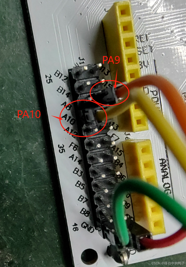
网友需要用PA9、PA10的I2C1,连接他的外设,这里我们用AT24C02作为演示,谁让我手上AT24C02散件太多呢?而且也只有这个EEPROM最简单常见了。
【原理图】

【硬件连接】
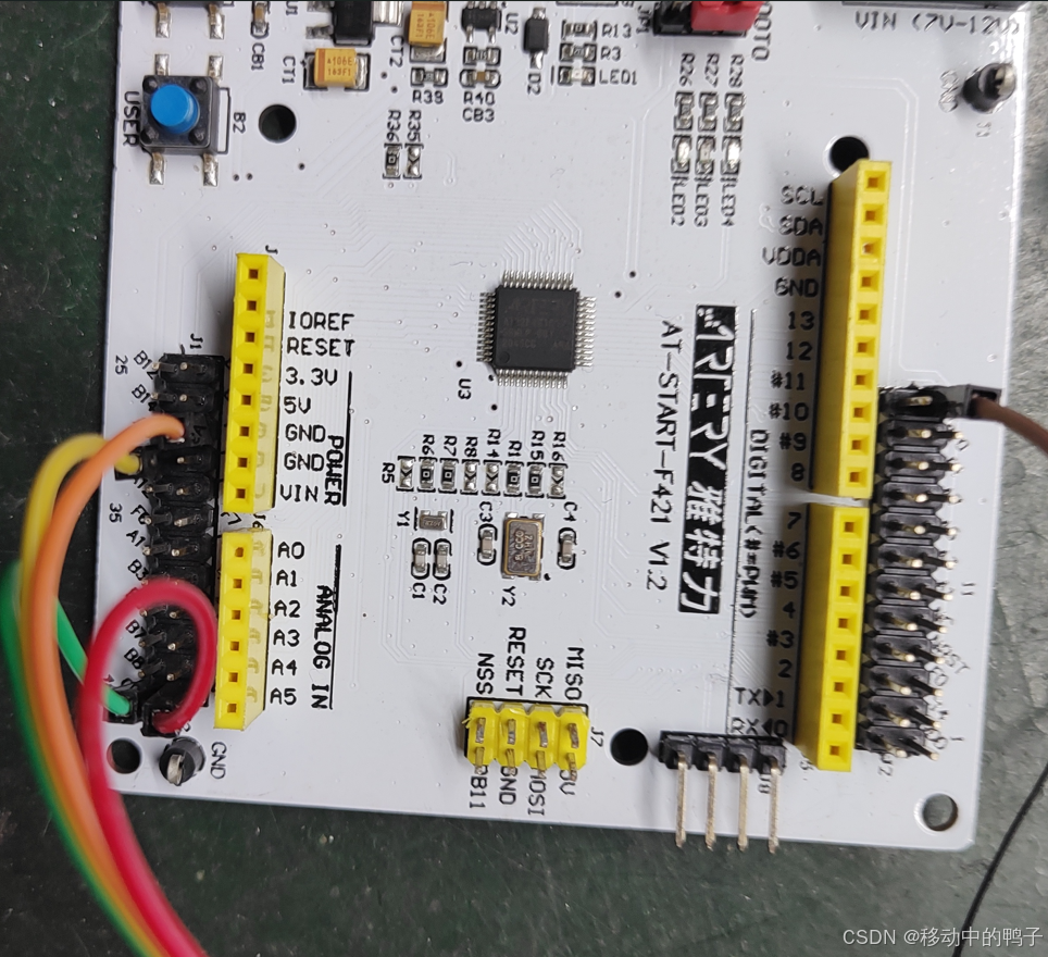
开发板用的是官方的《AT_START_F421_V1.2》,必须吐槽官方的设计,开发板上连个I2C外设都没有,好歹搞个AT24C0x上去呀,几个钱都省,印证了雅特力的应用设计能力很一般,对产品应用场景缺少经验。所以只能自己飞一块AT24C02了。
【软件设计】
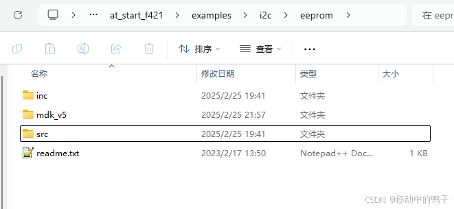
代码直接用官方BSP库里面的示例“eeprom”,路径为:
AT32F421_Firmware_Library_V2.1.2\project\at_start_f421\examples\i2c\eeprom
最后我会贴出改的源码,“伸手党”最喜欢了。
【常规软件修改过程】
这里我先说一下常规的操作,让读者也能复现失败的现象。
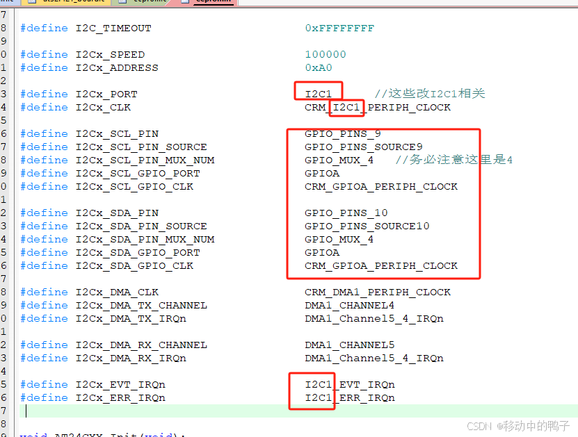
官方提供的eeprom案例,用的是PB10、PB11的I2C2,(但是官方这个readme.txt里面说是I2C1,加班忘了改的吧?),所以第一步就应该是把I2C2改为我们需要的PA9、PA10对应的I2C1,例如:
按理说这样改之后就能正常使用I2C1了,但是实际是不行的,I2C1没有任何反应。
【解决历程】
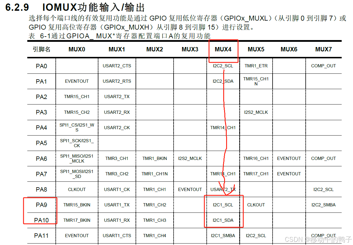
1. 有些同学可能会没注意421有很多的输入/输出复用器(IOMUX),查看《AT32F421技术手册_CH_V2.02.pdf》78页,6.2.9章节“IOMUX功能输入/输出”,看看是不是设置错了。由下图可知,一共有8个MUX,PA9和PA10必须配置为4号,那我的代码没错。
2. 继续认真查阅芯片数据手册《AT32F421数据手册_V2.01_CH.pdf》,PA9、PA10是这样描述的:
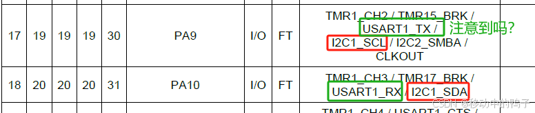
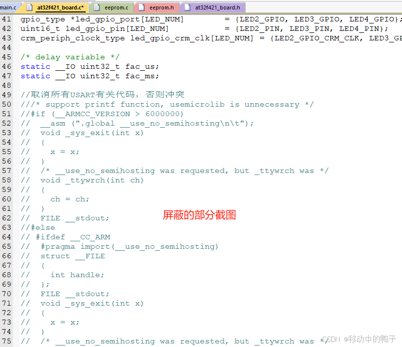
啊??我竟然忘记PA9和PA10是复用了串口1(USART1)?原来,由于我的设计基本避开利用串口1,所以已经陌生。那问题一定是USART1被占用了!所以,先屏蔽掉所有跟串口1有关的代码(源码后面附上):
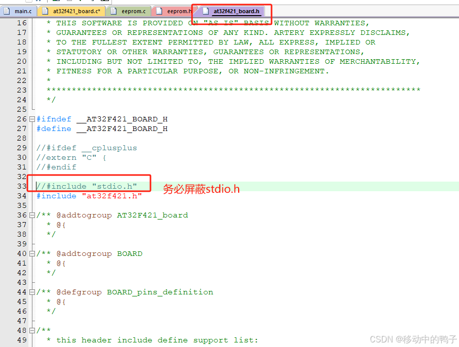
"at32f421_board.c"的50行起到146行直接屏蔽,并且务必屏蔽“at32f421_board.h”的#include "stdio.h"。
奇迹并没有发生!失败了。
3. 再次检查AT24C02芯片焊接情况,上拉电阻接触良好,8根脚的电平正常。再次检查I2C其他参考示例的代码,从中寻找差异的地方,可惜,根本没有用到PA9、PA10这个I2C1,都是些PB6、PB7,还有I2C2的等等。
(大约2小时后......)
4. 不如去官网查查资料,我首先搜索了I2C1的资料,无果。忽然灵机一动,搜索PA9怎么样?
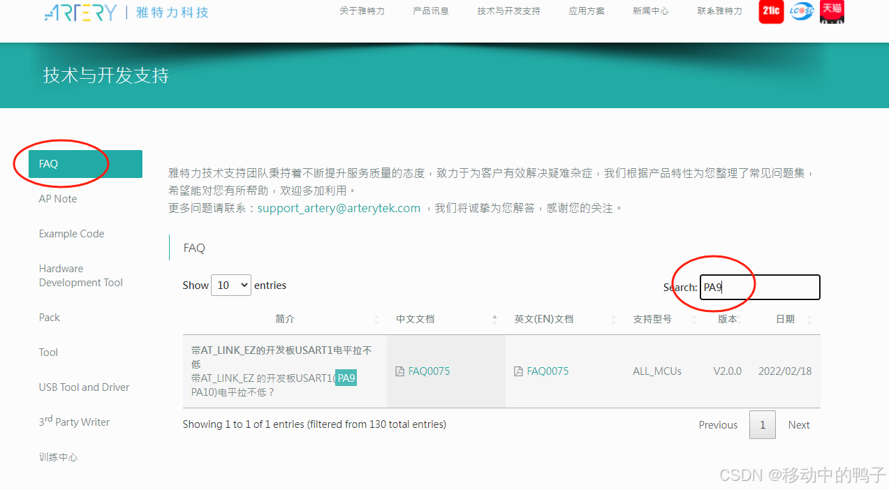
在技术文章没有搜到,倒是在FAQ里面找到一篇Questions:《带 AT_LINK_EZ 的开发板 USART1 (PA9 PA10)电平拉不低?》,啥玩意儿不知道,点开看看:
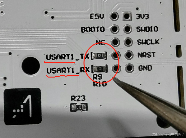
看到这个问答,我才恍然大悟,这个串口已经被AT-LINK占用鸟!!!再检查一下开发板,发现“罪魁祸首”了,发现了R9、R10两个0Ω短接:
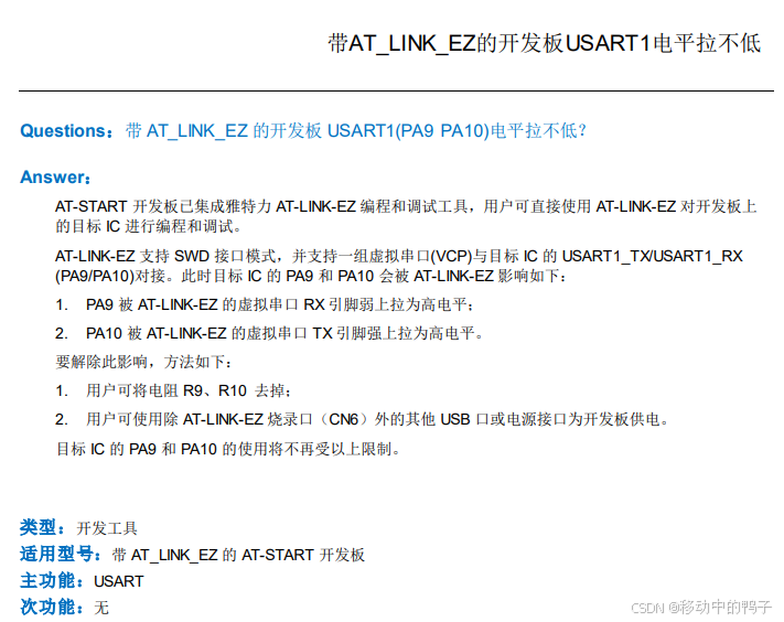
好了,按官方说法是:
要解除此影响,方法如下:
1. 用户可将电阻 R9、R10 去掉;
2. 用户可使用除 AT-LINK-EZ 烧录口(CN6)外的其他 USB 口或电源接口为开发板供电。
对我来说,没有方法2,只有方法1,必须得铲掉它!铲掉铲掉,统统铲掉!
最后跑一遍程序,成功了!
终于如释重负,赶紧联系网友发资料发源码,甚至还问了对方“是否需要开发板”(真诚),那位网友还是很有礼貌地表达了谢意。
【总结】
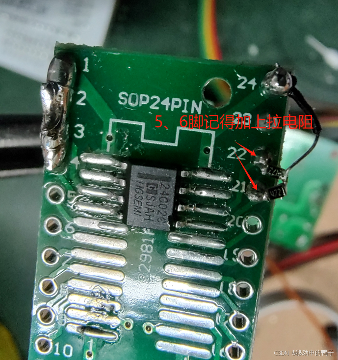
1. I2C必须外部带上拉电阻,阻值4.7K为宜。
2. 记得修改所有的官方源码的I2C2为I2C1,并修改引脚的编号和MUX_4
3. 屏蔽stdio.h,以及所有USART1的代码
4. 开发板的R9、R10(背面)要么铲掉,要么额外给DC头供电,不用自带的AT-LINK-EZ。
【涉及修改的源码】
“main.c"
/***************************************************************************** @file     main.c* @brief    main program**************************************************************************这个例程用I2C1测试写入8字节内容,并且读出后对比是否一致。每次开发板上的按键按下1次就执行一次上述动作*/#include "at32f421_board.h"
#include "at32f421_clock.h"
#include "i2c_application.h"
#include "eeprom.h"#define BUF_SIZE                         8//示例写入的内容缓存
uint8_t write_buf[BUF_SIZE] = {0x01, 0x02, 0x03, 0x04, 0x05, 0x06, 0x07, 0x08};
//示例读出的内容缓存
uint8_t read_buf[BUF_SIZE] = {0};//这个函数用来比较写入EEPROM和读出是否一致
uint32_t buffer_compare(uint8_t* buffer1, uint8_t* buffer2, uint32_t len)
{uint32_t i;for(i = 0; i < len; i++){if(buffer1[i] != buffer2[i]){return 1;}}return 0;
}
/*** @brief  main function.* @param  none* @retval none*/
int main(void)
{/* config nvic priority group */nvic_priority_group_config(NVIC_PRIORITY_GROUP_4);system_clock_config();at32_board_init();//注意:由于这里用的是PA9、PA10做I2C,跟USART1冲突了,所以USART1不能用,或者将USART1映射到别的脚AT24CXX_Init(); //初始化AT24C02while(1){// 等待按键被按下,开发板上是PA0while(at32_button_press() != USER_BUTTON){}//写入预设的值到地址0AT24CXX_Write(0,write_buf,BUF_SIZE);delay_ms(5);//写完又读出到temp缓存,从地址0开始AT24CXX_Read(0,read_buf,BUF_SIZE);//如果写入失败,这里读出的应该全00或全FF,//对比一下效果if((buffer_compare(write_buf, read_buf, BUF_SIZE) == 0)){at32_led_on(LED4);//开发板的绿灯闪delay_ms(500);at32_led_off(LED4);}else{at32_led_on(LED2);//开发的红灯闪delay_ms(500);at32_led_off(LED2);}}
}/*** @}*//*** @}*/
"eeprom.h"----驱动AT24C02
#ifndef __EEPROM_H
#define __EEPROM_H
#include "stdint.h"#define AT24C01		127
#define AT24C02		255					  //定义芯片容量
#define AT24C04		511
#define AT24C08		1023
#define AT24C16		2047
#define AT24C32		4095
#define AT24C64	    8191
#define AT24C128	16383
#define AT24C256	32767#define EE_TYPE AT24C02					 //更换芯片记得改这个型号#define I2C_TIMEOUT                      0xFFFFFFFF#define I2Cx_SPEED                       100000
#define I2Cx_ADDRESS                     0xA0#define I2Cx_PORT                        I2C1      //这些改I2C1相关
#define I2Cx_CLK                         CRM_I2C1_PERIPH_CLOCK#define I2Cx_SCL_PIN                     GPIO_PINS_9
#define I2Cx_SCL_PIN_SOURCE              GPIO_PINS_SOURCE9
#define I2Cx_SCL_PIN_MUX_NUM             GPIO_MUX_4   //务必注意这里是4
#define I2Cx_SCL_GPIO_PORT               GPIOA
#define I2Cx_SCL_GPIO_CLK                CRM_GPIOA_PERIPH_CLOCK#define I2Cx_SDA_PIN                     GPIO_PINS_10
#define I2Cx_SDA_PIN_SOURCE              GPIO_PINS_SOURCE10
#define I2Cx_SDA_PIN_MUX_NUM             GPIO_MUX_4
#define I2Cx_SDA_GPIO_PORT               GPIOA
#define I2Cx_SDA_GPIO_CLK                CRM_GPIOA_PERIPH_CLOCK#define I2Cx_DMA_CLK                     CRM_DMA1_PERIPH_CLOCK
#define I2Cx_DMA_TX_CHANNEL              DMA1_CHANNEL4
#define I2Cx_DMA_TX_IRQn                 DMA1_Channel5_4_IRQn#define I2Cx_DMA_RX_CHANNEL              DMA1_CHANNEL5
#define I2Cx_DMA_RX_IRQn                 DMA1_Channel5_4_IRQn#define I2Cx_EVT_IRQn                    I2C1_EVT_IRQn
#define I2Cx_ERR_IRQn                    I2C1_ERR_IRQnvoid AT24CXX_Init(void);
void AT24CXX_Write(uint16_t iAddress, uint8_t *buf, uint32_t length);
void AT24CXX_Read(uint16_t iAddress, uint8_t *buf, int32_t length);#endif
"eeprom.c"----驱动AT24C02
#include "at32f421_board.h"
#include "at32f421_clock.h"
#include "i2c_application.h"
#include "eeprom.h"//这个必须定义,大概是用于区分哪个I2C对象
i2c_handle_type hi2cx;void error_handler(uint32_t error_code);
void i2c_lowlevel_init(i2c_handle_type* hi2c);/*** @brief  error handler program* @param  i2c_status* @retval none*/
void error_handler(uint32_t error_code)
{//while(1)//{//at32_led_toggle(LED2);//delay_ms(500);//}
}
/*** @brief  initializes peripherals used by the i2c.* @param  none* @retval none*/
void i2c_lowlevel_init(i2c_handle_type* hi2c)
{gpio_init_type gpio_initstructure;if(hi2c->i2cx == I2Cx_PORT){/* i2c periph clock enable */crm_periph_clock_enable(I2Cx_CLK, TRUE);crm_periph_clock_enable(I2Cx_SCL_GPIO_CLK, TRUE);crm_periph_clock_enable(I2Cx_SDA_GPIO_CLK, TRUE);/* gpio configuration */gpio_initstructure.gpio_out_type       = GPIO_OUTPUT_OPEN_DRAIN;gpio_initstructure.gpio_pull           = GPIO_PULL_UP;gpio_initstructure.gpio_mode           = GPIO_MODE_MUX;gpio_initstructure.gpio_drive_strength = GPIO_DRIVE_STRENGTH_MODERATE;/* configure i2c pins: scl */gpio_initstructure.gpio_pins = I2Cx_SCL_PIN;gpio_init(I2Cx_SCL_GPIO_PORT, &gpio_initstructure);gpio_pin_mux_config(I2Cx_SCL_GPIO_PORT, I2Cx_SCL_PIN_SOURCE, I2Cx_SCL_PIN_MUX_NUM);gpio_pin_mux_config(GPIOA, GPIO_PINS_SOURCE9, GPIO_MUX_4);/* configure i2c pins: sda */gpio_initstructure.gpio_pins = I2Cx_SDA_PIN;gpio_init(I2Cx_SDA_GPIO_PORT, &gpio_initstructure);gpio_pin_mux_config(I2Cx_SDA_GPIO_PORT, I2Cx_SDA_PIN_SOURCE, I2Cx_SDA_PIN_MUX_NUM);gpio_pin_mux_config(GPIOA, GPIO_PINS_SOURCE10, GPIO_MUX_4);/* configure and enable i2c dma channel interrupt */nvic_irq_enable(I2Cx_DMA_TX_IRQn, 0, 0);nvic_irq_enable(I2Cx_DMA_RX_IRQn, 0, 0);/* configure and enable i2c interrupt */nvic_irq_enable(I2Cx_EVT_IRQn, 0, 0);nvic_irq_enable(I2Cx_ERR_IRQn, 0, 0);/* i2c dma tx and rx channels configuration *//* enable the dma clock */crm_periph_clock_enable(I2Cx_DMA_CLK, TRUE);/* i2c dma channel configuration */dma_reset(hi2c->dma_tx_channel);dma_reset(hi2c->dma_rx_channel);hi2c->dma_tx_channel = I2Cx_DMA_TX_CHANNEL;hi2c->dma_rx_channel = I2Cx_DMA_RX_CHANNEL;dma_default_para_init(&hi2c->dma_init_struct);hi2c->dma_init_struct.peripheral_inc_enable    = FALSE;hi2c->dma_init_struct.memory_inc_enable        = TRUE;hi2c->dma_init_struct.peripheral_data_width    = DMA_PERIPHERAL_DATA_WIDTH_BYTE;hi2c->dma_init_struct.memory_data_width        = DMA_MEMORY_DATA_WIDTH_BYTE;hi2c->dma_init_struct.loop_mode_enable         = FALSE;hi2c->dma_init_struct.priority                 = DMA_PRIORITY_LOW;hi2c->dma_init_struct.direction                = DMA_DIR_MEMORY_TO_PERIPHERAL;dma_init(hi2c->dma_tx_channel, &hi2c->dma_init_struct);dma_init(hi2c->dma_rx_channel, &hi2c->dma_init_struct);i2c_init(hi2c->i2cx, I2C_FSMODE_DUTY_2_1, I2Cx_SPEED);i2c_own_address1_set(hi2c->i2cx, I2C_ADDRESS_MODE_7BIT, I2Cx_ADDRESS);}
}/****************************************************************
*函数:AT24CXX_Init
*功能:初始化EEPROM
*参数:无
*
****************************************************************/
void AT24CXX_Init(void)
{hi2cx.i2cx = I2Cx_PORT;i2c_config(&hi2cx);
}/****************************************************************
*函数:AT24CXX_Write
*功能:写入EEPROM
*参数:buf--写入的内容,iAddress--地址,length--写入的内容长度
*
****************************************************************/
void AT24CXX_Write(uint16_t iAddress, uint8_t *buf, uint32_t length)
{u8 i=0;  i2c_status_type i2c_status;if(iAddress >  EE_TYPE){return;}if(iAddress + length >EE_TYPE){length=EE_TYPE-iAddress;}for(i=0;i<length;i+=8){	if(length-i>8){				if((i2c_status = i2c_memory_write(&hi2cx, I2C_MEM_ADDR_WIDIH_8, I2Cx_ADDRESS, iAddress+i, &buf[i], 8, I2C_TIMEOUT)) != I2C_OK){error_handler(i2c_status);}}else{if((i2c_status = i2c_memory_write(&hi2cx, I2C_MEM_ADDR_WIDIH_8, I2Cx_ADDRESS, iAddress+i, &buf[i], length-i, I2C_TIMEOUT)) != I2C_OK){error_handler(i2c_status);}}delay_ms(5);}
}/****************************************************************
*函数:AT24CXX_Read
*功能:读出EEPROM
*参数:buf--读出的内容,iAddress--地址,length--读出的内容长度
*
****************************************************************/
void AT24CXX_Read(uint16_t iAddress, uint8_t *buf, int32_t length)
{                    u8 i=0;  i2c_status_type i2c_status;for(i=0;i<length;i+=8){	if(length-i>8){				if((i2c_status = i2c_memory_read(&hi2cx, I2C_MEM_ADDR_WIDIH_8, I2Cx_ADDRESS, iAddress+i, &buf[i], 8, I2C_TIMEOUT)) != I2C_OK){error_handler(i2c_status);}}else{if((i2c_status = i2c_memory_read(&hi2cx, I2C_MEM_ADDR_WIDIH_8, I2Cx_ADDRESS, iAddress+i, &buf[i], length-i, I2C_TIMEOUT)) != I2C_OK){error_handler(i2c_status);}}delay_ms(5);}}
”at32f421_board.h“
/***************************************************************************** @file     at32f421_board.h* @brief    header file for at-start board. set of firmware functions to*           manage leds and push-button. initialize delay function.***************************************************************************                       Copyright notice & Disclaimer** The software Board Support Package (BSP) that is made available to* download from Artery official website is the copyrighted work of Artery.* Artery authorizes customers to use, copy, and distribute the BSP* software and its related documentation for the purpose of design and* development in conjunction with Artery microcontrollers. Use of the* software is governed by this copyright notice and the following disclaimer.** THIS SOFTWARE IS PROVIDED ON "AS IS" BASIS WITHOUT WARRANTIES,* GUARANTEES OR REPRESENTATIONS OF ANY KIND. ARTERY EXPRESSLY DISCLAIMS,* TO THE FULLEST EXTENT PERMITTED BY LAW, ALL EXPRESS, IMPLIED OR* STATUTORY OR OTHER WARRANTIES, GUARANTEES OR REPRESENTATIONS,* INCLUDING BUT NOT LIMITED TO, THE IMPLIED WARRANTIES OF MERCHANTABILITY,* FITNESS FOR A PARTICULAR PURPOSE, OR NON-INFRINGEMENT.****************************************************************************/#ifndef __AT32F421_BOARD_H
#define __AT32F421_BOARD_H//#ifdef __cplusplus
//extern "C" {
//#endif//#include "stdio.h"
#include "at32f421.h"/** @addtogroup AT32F421_board* @{*//** @addtogroup BOARD* @{*//** @defgroup BOARD_pins_definition* @{*//*** this header include define support list:* 1. at-start-f421 v1.x boards* if define AT_START_F421_V1, the header file support at-start-f421 v1.x board*///#if !defined (AT_START_F421_V1)
#error "please select first the board at-start device used in your application (in at32f421_board.h file)"
//#endif/******************** define led ********************/
typedef enum
{LED2                                   = 0,LED3                                   = 1,LED4                                   = 2
} led_type;#define LED_NUM                          3#if defined (AT_START_F421_V1)
#define LED2_PIN                         GPIO_PINS_6
#define LED2_GPIO                        GPIOF
#define LED2_GPIO_CRM_CLK                CRM_GPIOF_PERIPH_CLOCK#define LED3_PIN                         GPIO_PINS_7
#define LED3_GPIO                        GPIOF
#define LED3_GPIO_CRM_CLK                CRM_GPIOF_PERIPH_CLOCK#define LED4_PIN                         GPIO_PINS_11
#define LED4_GPIO                        GPIOB
#define LED4_GPIO_CRM_CLK                CRM_GPIOB_PERIPH_CLOCK
#endif/**************** define print uart ******************/
//取消所有跟USART有关的代码
//#define PRINT_UART                       USART2
//#define PRINT_UART_CRM_CLK               CRM_USART2_PERIPH_CLOCK
//#define PRINT_UART_TX_PIN                GPIO_PINS_14
//#define PRINT_UART_TX_GPIO               GPIOA
//#define PRINT_UART_TX_GPIO_CRM_CLK       CRM_GPIOA_PERIPH_CLOCK
//#define PRINT_UART_TX_PIN_SOURCE         GPIO_PINS_SOURCE14
//#define PRINT_UART_TX_PIN_MUX_NUM        GPIO_MUX_1/******************* define button *******************/
typedef enum
{USER_BUTTON                            = 0,NO_BUTTON                              = 1
} button_type;#define USER_BUTTON_PIN                  GPIO_PINS_0
#define USER_BUTTON_PORT                 GPIOA
#define USER_BUTTON_CRM_CLK              CRM_GPIOA_PERIPH_CLOCK/*** @}*//** @defgroup BOARD_exported_functions* @{*//******************** functions ********************/
void at32_board_init(void);/* led operation function */
void at32_led_init(led_type led);
void at32_led_on(led_type led);
void at32_led_off(led_type led);
void at32_led_toggle(led_type led);/* button operation function */
void at32_button_init(void);
button_type at32_button_press(void);
uint8_t at32_button_state(void);/* delay function */
void delay_init(void);
void delay_us(uint32_t nus);
void delay_ms(uint16_t nms);
void delay_sec(uint16_t sec);/* printf uart init function */
//void uart_print_init(uint32_t baudrate);/*** @}*//*** @}*//*** @}*///#ifdef __cplusplus
//}
//#endif#endif
"at32f421_board.c"
/***************************************************************************** @file     at32f421_board.c* @brief    set of firmware functions to manage leds and push-button.*           initialize delay function.***************************************************************************                       Copyright notice & Disclaimer** The software Board Support Package (BSP) that is made available to* download from Artery official website is the copyrighted work of Artery.* Artery authorizes customers to use, copy, and distribute the BSP* software and its related documentation for the purpose of design and* development in conjunction with Artery microcontrollers. Use of the* software is governed by this copyright notice and the following disclaimer.** THIS SOFTWARE IS PROVIDED ON "AS IS" BASIS WITHOUT WARRANTIES,* GUARANTEES OR REPRESENTATIONS OF ANY KIND. ARTERY EXPRESSLY DISCLAIMS,* TO THE FULLEST EXTENT PERMITTED BY LAW, ALL EXPRESS, IMPLIED OR* STATUTORY OR OTHER WARRANTIES, GUARANTEES OR REPRESENTATIONS,* INCLUDING BUT NOT LIMITED TO, THE IMPLIED WARRANTIES OF MERCHANTABILITY,* FITNESS FOR A PARTICULAR PURPOSE, OR NON-INFRINGEMENT.****************************************************************************/#include "at32f421_board.h"/** @addtogroup AT32F421_board* @{*//** @defgroup BOARD* @brief onboard periph driver* @{*//* delay macros */
#define STEP_DELAY_MS                    50/* at-start led resouce array */
gpio_type *led_gpio_port[LED_NUM]        = {LED2_GPIO, LED3_GPIO, LED4_GPIO};
uint16_t led_gpio_pin[LED_NUM]           = {LED2_PIN, LED3_PIN, LED4_PIN};
crm_periph_clock_type led_gpio_crm_clk[LED_NUM] = {LED2_GPIO_CRM_CLK, LED3_GPIO_CRM_CLK, LED4_GPIO_CRM_CLK};/* delay variable */
static __IO uint32_t fac_us;
static __IO uint32_t fac_ms;//取消所有USART有关代码,否则冲突
///* support printf function, usemicrolib is unnecessary */
//#if (__ARMCC_VERSION > 6000000)
//  __asm (".global __use_no_semihosting\n\t");
//  void _sys_exit(int x)
//  {
//    x = x;
//  }
//  /* __use_no_semihosting was requested, but _ttywrch was */
//  void _ttywrch(int ch)
//  {
//    ch = ch;
//  }
//  FILE __stdout;
//#else
// #ifdef __CC_ARM
//  #pragma import(__use_no_semihosting)
//  struct __FILE
//  {
//    int handle;
//  };
//  FILE __stdout;
//  void _sys_exit(int x)
//  {
//    x = x;
//  }
//  /* __use_no_semihosting was requested, but _ttywrch was */
//  void _ttywrch(int ch)
//  {
//    ch = ch;
//  }
// #endif
//#endif//#if defined (__GNUC__) && !defined (__clang__)
//  //#define PUTCHAR_PROTOTYPE int __io_putchar(int ch)
//#else
//  //#define PUTCHAR_PROTOTYPE int fputc(int ch, FILE *f)
//#endif///**
//  * @brief  retargets the c library printf function to the usart.
//  * @param  none
//  * @retval none
//  */
//PUTCHAR_PROTOTYPE
//{
//  while(usart_flag_get(PRINT_UART, USART_TDBE_FLAG) == RESET);
//  usart_data_transmit(PRINT_UART, ch);
//  return ch;
//}//#if defined (__GNUC__) && !defined (__clang__)
//int _write(int fd, char *pbuffer, int size)
//{
//  for(int i = 0; i < size; i ++)
//  {
//    __io_putchar(*pbuffer++);
//  }//  return size;
//}
//#endif///**
//  * @brief  initialize uart
//  * @param  baudrate: uart baudrate
//  * @retval none
//  */
//void uart_print_init(uint32_t baudrate)
//{
//  gpio_init_type gpio_init_struct;//#if defined (__GNUC__) && !defined (__clang__)
//  setvbuf(stdout, NULL, _IONBF, 0);
//#endif//  /* enable the uart and gpio clock */
//  crm_periph_clock_enable(PRINT_UART_CRM_CLK, TRUE);
//  crm_periph_clock_enable(PRINT_UART_TX_GPIO_CRM_CLK, TRUE);//  gpio_default_para_init(&gpio_init_struct);//  /* configure the uart tx pin */
//  gpio_init_struct.gpio_drive_strength = GPIO_DRIVE_STRENGTH_STRONGER;
//  gpio_init_struct.gpio_out_type  = GPIO_OUTPUT_PUSH_PULL;
//  gpio_init_struct.gpio_mode = GPIO_MODE_MUX;
//  gpio_init_struct.gpio_pins = PRINT_UART_TX_PIN;
//  gpio_init_struct.gpio_pull = GPIO_PULL_NONE;
//  gpio_init(PRINT_UART_TX_GPIO, &gpio_init_struct);//  gpio_pin_mux_config(PRINT_UART_TX_GPIO, PRINT_UART_TX_PIN_SOURCE, PRINT_UART_TX_PIN_MUX_NUM);//  /* configure uart param */
//  usart_init(PRINT_UART, baudrate, USART_DATA_8BITS, USART_STOP_1_BIT);
//  usart_transmitter_enable(PRINT_UART, TRUE);
//  usart_enable(PRINT_UART, TRUE);
//}/*** @brief  board initialize interface init led and button* @param  none* @retval none*/
void at32_board_init()
{/* initialize delay function */delay_init();/* configure led in at_start_board */at32_led_init(LED2);at32_led_init(LED3);at32_led_init(LED4);at32_led_off(LED2);at32_led_off(LED3);at32_led_off(LED4);/* configure button in at_start board */at32_button_init();
}/*** @brief  configure button gpio* @param  button: specifies the button to be configured.* @retval none*/
void at32_button_init(void)
{gpio_init_type gpio_init_struct;/* enable the button clock */crm_periph_clock_enable(USER_BUTTON_CRM_CLK, TRUE);/* set default parameter */gpio_default_para_init(&gpio_init_struct);/* configure button pin as input with pull-up/pull-down */gpio_init_struct.gpio_drive_strength = GPIO_DRIVE_STRENGTH_STRONGER;gpio_init_struct.gpio_out_type  = GPIO_OUTPUT_PUSH_PULL;gpio_init_struct.gpio_mode = GPIO_MODE_INPUT;gpio_init_struct.gpio_pins = USER_BUTTON_PIN;gpio_init_struct.gpio_pull = GPIO_PULL_DOWN;gpio_init(USER_BUTTON_PORT, &gpio_init_struct);
}/*** @brief  returns the selected button state* @param  none* @retval the button gpio pin value*/
uint8_t at32_button_state(void)
{return gpio_input_data_bit_read(USER_BUTTON_PORT, USER_BUTTON_PIN);
}/*** @brief  returns which button have press down* @param  none* @retval the button have press down*/
button_type at32_button_press()
{static uint8_t pressed = 1;/* get button state in at_start board */if((pressed == 1) && (at32_button_state() != RESET)){/* debounce */pressed = 0;delay_ms(10);if(at32_button_state() != RESET)return USER_BUTTON;}else if(at32_button_state() == RESET){pressed = 1;}return NO_BUTTON;
}/*** @brief  configure led gpio* @param  led: specifies the led to be configured.* @retval none*/
void at32_led_init(led_type led)
{gpio_init_type gpio_init_struct;/* enable the led clock */crm_periph_clock_enable(led_gpio_crm_clk[led], TRUE);/* set default parameter */gpio_default_para_init(&gpio_init_struct);/* configure the led gpio */gpio_init_struct.gpio_drive_strength = GPIO_DRIVE_STRENGTH_STRONGER;gpio_init_struct.gpio_out_type  = GPIO_OUTPUT_PUSH_PULL;gpio_init_struct.gpio_mode = GPIO_MODE_OUTPUT;gpio_init_struct.gpio_pins = led_gpio_pin[led];gpio_init_struct.gpio_pull = GPIO_PULL_NONE;gpio_init(led_gpio_port[led], &gpio_init_struct);
}/*** @brief  turns selected led on.* @param  led: specifies the led to be set on.*   this parameter can be one of following parameters:*     @arg LED2*     @arg LED3*     @arg LED4* @retval none*/
void at32_led_on(led_type led)
{if(led > (LED_NUM - 1))return;if(led_gpio_pin[led])led_gpio_port[led]->clr = led_gpio_pin[led];
}/*** @brief  turns selected led off.* @param  led: specifies the led to be set off.*   this parameter can be one of following parameters:*     @arg LED2*     @arg LED3*     @arg LED4* @retval none*/
void at32_led_off(led_type led)
{if(led > (LED_NUM - 1))return;if(led_gpio_pin[led])led_gpio_port[led]->scr = led_gpio_pin[led];
}/*** @brief  turns selected led toggle.* @param  led: specifies the led to be set off.*   this parameter can be one of following parameters:*     @arg LED2*     @arg LED3*     @arg LED4* @retval none*/
void at32_led_toggle(led_type led)
{if(led > (LED_NUM - 1))return;if(led_gpio_pin[led])led_gpio_port[led]->odt ^= led_gpio_pin[led];
}/*** @brief  initialize delay function* @param  none* @retval none*/
void delay_init()
{/* configure systick */systick_clock_source_config(SYSTICK_CLOCK_SOURCE_AHBCLK_NODIV);fac_us = system_core_clock / (1000000U);fac_ms = fac_us * (1000U);
}/*** @brief  inserts a delay time.* @param  nus: specifies the delay time length, in microsecond.* @retval none*/
void delay_us(uint32_t nus)
{uint32_t temp = 0;SysTick->LOAD = (uint32_t)(nus * fac_us);SysTick->VAL = 0x00;SysTick->CTRL |= SysTick_CTRL_ENABLE_Msk ;do{temp = SysTick->CTRL;}while((temp & 0x01) && !(temp & (1 << 16)));SysTick->CTRL &= ~SysTick_CTRL_ENABLE_Msk;SysTick->VAL = 0x00;
}/*** @brief  inserts a delay time.* @param  nms: specifies the delay time length, in milliseconds.* @retval none*/
void delay_ms(uint16_t nms)
{uint32_t temp = 0;while(nms){if(nms > STEP_DELAY_MS){SysTick->LOAD = (uint32_t)(STEP_DELAY_MS * fac_ms);nms -= STEP_DELAY_MS;}else{SysTick->LOAD = (uint32_t)(nms * fac_ms);nms = 0;}SysTick->VAL = 0x00;SysTick->CTRL |= SysTick_CTRL_ENABLE_Msk;do{temp = SysTick->CTRL;}while((temp & 0x01) && !(temp & (1 << 16)));SysTick->CTRL &= ~SysTick_CTRL_ENABLE_Msk;SysTick->VAL = 0x00;}
}/*** @brief  inserts a delay time.* @param  sec: specifies the delay time, in seconds.* @retval none*/
void delay_sec(uint16_t sec)
{uint16_t index;for(index = 0; index < sec; index++){delay_ms(500);delay_ms(500);}
}/*** @}*//*** @}*/
希望雅特力能再进步些。