VLAN和Trunk实验
VLAN和Trunk实验
实验拓扑
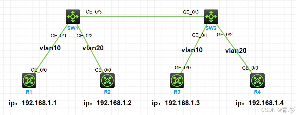
实验需求
1.按照图示给所有路由器(此处充当pc机)配置IP地址
2.SW1和SW2上分别创建vlan10和vlan20,要求R1和R3属于vlan10,R2和R4属于vlan20
3.SW1和SW2相连的接口配置类型为trunk类型,允许vlan10和vlan20通过
4.测试效果,同一vlan的路由器可以互通,不同vlan的路由器无法互通
实验步骤
1.路由器配置IP地址
在R1上
<H3C>system-view
System View: return to User View with Ctrl+Z.
[H3C]sysname R1
[R1]int g0/0
[R1-GigabitEthernet0/0]ip address 192.168.1.1 24
[R1-GigabitEthernet0/0]display ip interface brief
*down: administratively down
(s): spoofing  (l): loopback
Interface           Physical Protocol IP address/Mask    VPN instance Description
GE0/0               up       up       192.168.1.1/24     --           --
GE0/1               down     down     --                 --           --
GE0/2               down     down     --                 --           --
GE5/0               down     down     --                 --           --
GE5/1               down     down     --                 --           --
GE6/0               down     down     --                 --           --
GE6/1               down     down     --                 --           --
Ser1/0              down     down     --                 --           --
Ser2/0              down     down     --                 --           --
Ser3/0              down     down     --                 --           --
Ser4/0              down     down     --                 --           --
[R1-GigabitEthernet0/0]

在R2上
<H3C>system-view
System View: return to User View with Ctrl+Z.
[H3C]sysname R2
[R2]int g0/0
[R2-GigabitEthernet0/0]ip address 192.168.1.2 24
[R2-GigabitEthernet0/0]display ip interface brief
*down: administratively down
(s): spoofing  (l): loopback
Interface           Physical Protocol IP address/Mask    VPN instance Description
GE0/0               up       up       192.168.1.2/24     --           --
GE0/1               down     down     --                 --           --
GE0/2               down     down     --                 --           --
GE5/0               down     down     --                 --           --
GE5/1               down     down     --                 --           --
GE6/0               down     down     --                 --           --
GE6/1               down     down     --                 --           --
Ser1/0              down     down     --                 --           --
Ser2/0              down     down     --                 --           --
Ser3/0              down     down     --                 --           --
Ser4/0              down     down     --                 --           --
[R2-GigabitEthernet0/0]

在R3上
<H3C>system-view
System View: return to User View with Ctrl+Z.
[H3C]sysname R3
[R3]int g0/0
[R3-GigabitEthernet0/0]ip address 192.168.1.3 24
[R3-GigabitEthernet0/0]display ip interface brief
*down: administratively down
(s): spoofing  (l): loopback
Interface           Physical Protocol IP address/Mask    VPN instance Description
GE0/0               up       up       192.168.1.3/24     --           --
GE0/1               down     down     --                 --           --
GE0/2               down     down     --                 --           --
GE5/0               down     down     --                 --           --
GE5/1               down     down     --                 --           --
GE6/0               down     down     --                 --           --
GE6/1               down     down     --                 --           --
Ser1/0              down     down     --                 --           --
Ser2/0              down     down     --                 --           --
Ser3/0              down     down     --                 --           --
Ser4/0              down     down     --                 --           --
[R3-GigabitEthernet0/0]

在R4上
<H3C>system-view
System View: return to User View with Ctrl+Z.
[H3C]sysname R4
[R4]int g0/0
[R4-GigabitEthernet0/0]ip address 192.168.1.4 24
[R4-GigabitEthernet0/0]display ip interface brief
*down: administratively down
(s): spoofing  (l): loopback
Interface           Physical Protocol IP address/Mask    VPN instance Description
GE0/0               up       up       192.168.1.4/24     --           --
GE0/1               down     down     --                 --           --
GE0/2               down     down     --                 --           --
GE5/0               down     down     --                 --           --
GE5/1               down     down     --                 --           --
GE6/0               down     down     --                 --           --
GE6/1               down     down     --                 --           --
Ser1/0              down     down     --                 --           --
Ser2/0              down     down     --                 --           --
Ser3/0              down     down     --                 --           --
Ser4/0              down     down     --                 --           --
[R4-GigabitEthernet0/0]
2.测试四台路由器是否互通
在R1上测试
[R1]ping 192.168.1.2
Ping 192.168.1.2 (192.168.1.2): 56 data bytes, press CTRL+C to break
56 bytes from 192.168.1.2: icmp_seq=0 ttl=255 time=1.322 ms
56 bytes from 192.168.1.2: icmp_seq=1 ttl=255 time=0.704 ms
56 bytes from 192.168.1.2: icmp_seq=2 ttl=255 time=0.649 ms
56 bytes from 192.168.1.2: icmp_seq=3 ttl=255 time=0.407 ms
56 bytes from 192.168.1.2: icmp_seq=4 ttl=255 time=0.492 ms

--- Ping statistics for 192.168.1.2 ---
5 packet(s) transmitted, 5 packet(s) received, 0.0% packet loss
round-trip min/avg/max/std-dev = 0.407/0.715/1.322/0.322 ms
[R1]%Mar 13 15:33:42:421 2025 R1 PING/6/PING_STATISTICS: Ping statistics for 192.168.1.2: 5 packet(s) transmitted, 5 packet(s) received, 0.0% packet loss, round-trip min/avg/max/std-dev = 0.407/0.715/1.322/0.322 ms.

[R1]ping 192.168.1.3
Ping 192.168.1.3 (192.168.1.3): 56 data bytes, press CTRL+C to break
56 bytes from 192.168.1.3: icmp_seq=0 ttl=255 time=2.937 ms
56 bytes from 192.168.1.3: icmp_seq=1 ttl=255 time=1.287 ms
56 bytes from 192.168.1.3: icmp_seq=2 ttl=255 time=1.324 ms
56 bytes from 192.168.1.3: icmp_seq=3 ttl=255 time=0.909 ms
56 bytes from 192.168.1.3: icmp_seq=4 ttl=255 time=1.273 ms

--- Ping statistics for 192.168.1.3 ---
5 packet(s) transmitted, 5 packet(s) received, 0.0% packet loss
round-trip min/avg/max/std-dev = 0.909/1.546/2.937/0.712 ms
[R1]%Mar 13 15:33:46:677 2025 R1 PING/6/PING_STATISTICS: Ping statistics for 192.168.1.3: 5 packet(s) transmitted, 5 packet(s) received, 0.0% packet loss, round-trip min/avg/max/std-dev = 0.909/1.546/2.937/0.712 ms.

[R1]ping 192.168.1.4
Ping 192.168.1.4 (192.168.1.4): 56 data bytes, press CTRL+C to break
56 bytes from 192.168.1.4: icmp_seq=0 ttl=255 time=2.350 ms
56 bytes from 192.168.1.4: icmp_seq=1 ttl=255 time=1.049 ms
56 bytes from 192.168.1.4: icmp_seq=2 ttl=255 time=1.099 ms
56 bytes from 192.168.1.4: icmp_seq=3 ttl=255 time=1.308 ms
56 bytes from 192.168.1.4: icmp_seq=4 ttl=255 time=1.046 ms

--- Ping statistics for 192.168.1.4 ---
5 packet(s) transmitted, 5 packet(s) received, 0.0% packet loss
round-trip min/avg/max/std-dev = 1.046/1.370/2.350/0.499 ms
[R1]%Mar 13 15:33:50:508 2025 R1 PING/6/PING_STATISTICS: Ping statistics for 192.168.1.4: 5 packet(s) transmitted, 5 packet(s) received, 0.0% packet loss, round-trip min/avg/max/std-dev = 1.046/1.370/2.350/0.499 ms.
3.在交换机SW1和SW2上分别创建vlan10和vlan20,SW1和SW2都把g1/0/1接口加入vlan10,g1/0/2接口加入vlan20
在SW1上
<H3C>system-view
System View: return to User View with Ctrl+Z.
[H3C]sysname SW1
[SW1]vlan 10
[SW1-vlan10]port g1/0/1
[SW1-vlan10]qu
[SW1]vlan 20
[SW1-vlan20]port g1/0/2
[SW1-vlan20]qu
[SW1]

在SW2上
<H3C>system-view
System View: return to User View with Ctrl+Z.
[H3C]sysname SW2
[SW2]vlan 10
[SW2-vlan10]port g1/0/1
[SW2-vlan10]qu
[SW2]vlan 20
[SW2-vlan20]port g1/0/2
[SW2-vlan20]qu
[SW2]
4.SW1和SW2的g1/0/3接口都配置为trunk,允许vlan10和vlan20通过
在SW1上把g1/0/3接口配置为Trunk类型,并允许vlan10和vlan20通过
[SW1]int g1/0/3
[SW1-GigabitEthernet1/0/3]port link-type trunk        		//将接口类型改为trunk
[SW1-GigabitEthernet1/0/3]port trunk permit vlan 10 20 		//放行vlan10和vlan20
[SW1-GigabitEthernet1/0/3]display this						//查看当前接口下配置信息
#
interface GigabitEthernet1/0/3
 port link-mode bridge
 port link-type trunk
 port trunk permit vlan 1 10 20
 combo enable fiber
#
return
[SW1-GigabitEthernet1/0/3]

在SW2上把g1/0/3接口配置为Trunk类型,并允许vlan10和vlan20通过
[SW2]int g1/0/3
[SW2-GigabitEthernet1/0/3]port link-type trunk
[SW2-GigabitEthernet1/0/3]port trunk permit vlan 10 20
[SW2-GigabitEthernet1/0/3]display this
#
interface GigabitEthernet1/0/3
 port link-mode bridge
 port link-type trunk
 port trunk permit vlan 1 10 20
 combo enable fiber
#
return
[SW2-GigabitEthernet1/0/3]
5.测试结果,R1可以PING通R3,但无法PING通R2和R4
在R1上pingR2
[R1]ping 192.168.1.2
Ping 192.168.1.2 (192.168.1.2): 56 data bytes, press CTRL+C to break
Request time out
Request time out
Request time out
Request time out
Request time out

--- Ping statistics for 192.168.1.2 ---
5 packet(s) transmitted, 0 packet(s) received, 100.0% packet loss
[R1]%Mar 13 15:44:47:912 2025 R1 PING/6/PING_STATISTICS: Ping statistics for 192.168.1.2: 5 packet(s) transmitted, 0 packet(s) received, 100.0% packet loss.

在R1上pingR3
[R1]ping 192.168.1.3
Ping 192.168.1.3 (192.168.1.3): 56 data bytes, press CTRL+C to break
56 bytes from 192.168.1.3: icmp_seq=0 ttl=255 time=1.053 ms
56 bytes from 192.168.1.3: icmp_seq=1 ttl=255 time=0.615 ms
56 bytes from 192.168.1.3: icmp_seq=2 ttl=255 time=1.157 ms
56 bytes from 192.168.1.3: icmp_seq=3 ttl=255 time=1.041 ms
56 bytes from 192.168.1.3: icmp_seq=4 ttl=255 time=1.410 ms

--- Ping statistics for 192.168.1.3 ---
5 packet(s) transmitted, 5 packet(s) received, 0.0% packet loss
round-trip min/avg/max/std-dev = 0.615/1.055/1.410/0.257 ms
[R1]%Mar 13 15:45:13:276 2025 R1 PING/6/PING_STATISTICS: Ping statistics for 192.168.1.3: 5 packet(s) transmitted, 5 packet(s) received, 0.0% packet loss, round-trip min/avg/max/std-dev = 0.615/1.055/1.410/0.257 ms.

在R1上pingR4
[R1]ping 192.168.1.4
Ping 192.168.1.4 (192.168.1.4): 56 data bytes, press CTRL+C to break
Request time out
Request time out
Request time out
Request time out
Request time out

--- Ping statistics for 192.168.1.4 ---
5 packet(s) transmitted, 0 packet(s) received, 100.0% packet loss
[R1]%Mar 13 15:45:46:526 2025 R1 PING/6/PING_STATISTICS: Ping statistics for 192.168.1.4: 5 packet(s) transmitted, 0 packet(s) received, 100.0% packet loss.
实验效果成功实现