FPGA设计实践之电子秒表设计(VHDL版——ISE14.7)
前言
本设计使用VHDL语言在虚拟机(WIN7)上开发,环境为ISE14.7,开发板为Diligent NEXY3(板上时钟为100MHz),Spartan6内核,型号为XC6SLX16(-3),仅供参考学习使用。
一、设计实现功能
实现数字秒表设计并在开发板显示。
(1)采用层次化设计方式,将设计分为三个模块,分别是分频模块、计数模块、数码管显示模块,顶层模块例化这三个模块。
(2)秒表计数范围:00’到59’;
(3)带有复位、启动/停止功能。
拓展功能:
- 不仅能正向计数,也能反向计数。增加置数功能,通过按键置数,能将计数值直接设置成指定的数字,采用6个拨码开关(置数范围从0-2^6)置数。
- LED控制模块,判断计数情况,当计数值处于不同的区间时,点亮相应数量的LED以提示计数进度。
- 串口输出功能,将计数状态数值即时传出串口TX,对LCD屏幕进行控制,实时显示计数状态。
二、代码编写及分析
综合设计采用的是模块化设计,顶层设计(TOP)将元件(Component)进行例化。整体模块分布关系如流程图所示:
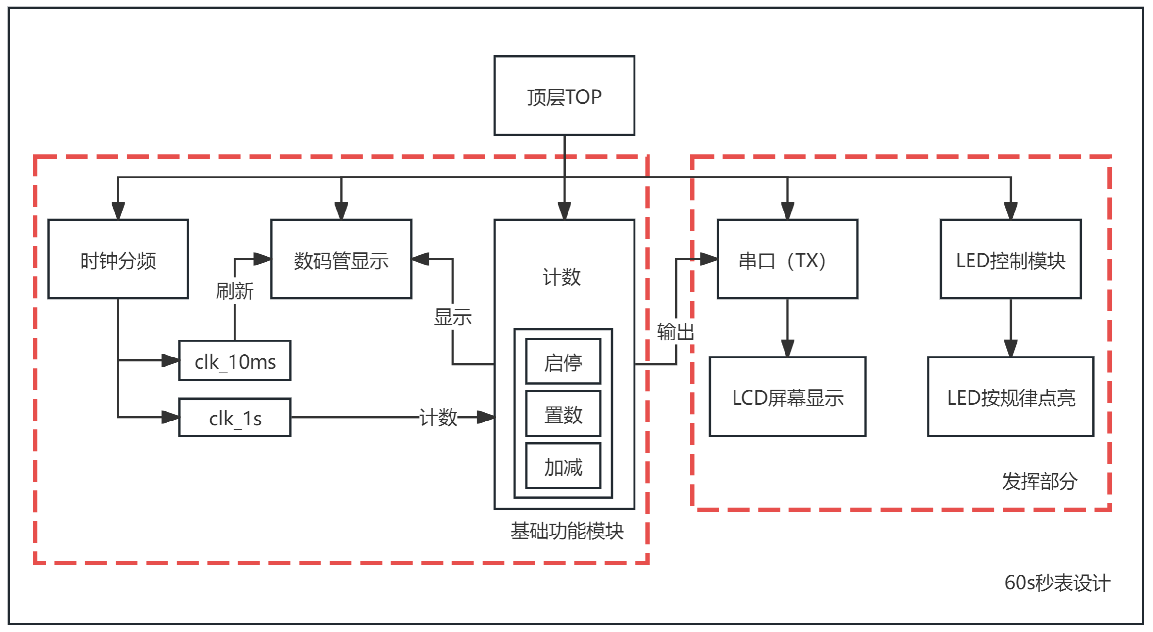
总体结构如图所示
按照设计要求主要包含以上模块:
核心部分:
1、时钟分频模块:将100MHz的时钟通过计数器计数的方式,分频出对应频率的时钟:10ms、1s,10ms用于数码管刷新显示,1s用于时钟的标准计数。分频器将晶振产生的100MHz 的方波信号作为该模块的时钟信号,计算并设置对应的计数长度,设置对应的寄存器大小。当检测到一次上升沿计数变量cnt就自增1,当数值达到设定值的时候就将输出端的电平翻转,以此达到分频产生方波的效果。
2、数码管显示模块:对数码管的不同位进行刷新显示。共有两个进程:进程1根据翻转时钟进行数码管位选的切换,进程2根据进程1显示的数码管位选状态显示对应的数值(段选)。
3、计数模块:主要是if逻辑的嵌套,实现异步清零、启停,同步置数、同步加减控制(异步即为按键/开关即时控制,同步则需要在时钟上升沿之后才有效)。思路与之前构建十进制计数器是一样的,只不过现在是控制两位数显示。通过除法计算和取模计算的方式可以简单得到计数值的十位和个位。
4、串口输出模块:只需要使能一个TX口即可,绑定引脚也没有特殊的需求,任何一个普通引脚都可以用于串口时序的设计,体现了FPGA不同于单片机的特点。本部分的设计参考了网络的串口Usart例程进行设计,可以轻松修改串口的参数。外接LCD屏幕设计,LCD屏幕的设计此处略去,主要是通过串口输出对应格式的文本数据,以起到控制LCD的功能。
5、LED控制模块:这个模块更简单,只需要对计数数值进行简单的判断即可,起到一个丰富板上使用资源的效果。主要是通过一系列if逻辑,判断计数值的状态,亮起对应的LED。
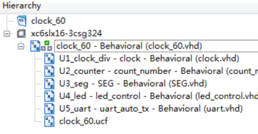
ISE14.7中显示模块例化如上图所示
代码块:
一、顶层模块
library IEEE;
use IEEE.STD_LOGIC_1164.ALL;
use IEEE.NUMERIC_STD.ALL;
use IEEE.STD_LOGIC_UNSIGNED.ALL;  entity clock_60 is
Port(sys_clk : in STD_LOGIC;enable     : in STD_LOGIC;rst         : in STD_LOGIC;y         : out STD_LOGIC_VECTOR(6 downto 0);SEG_W     : out STD_LOGIC_VECTOR(3 downto 0);led         : out STD_LOGIC_VECTOR(5 downto 0);SEL     : in  STD_LOGIC;             LD      : in  STD_LOGIC;             Data    : in  STD_LOGIC_VECTOR(5 downto 0); tx      : out STD_LOGIC                 -- UART TX 输出
);
end clock_60;
architecture Behavioral of clock_60 is
Component count_number is
Port(clk_1s  : in  STD_LOGIC;              -- 输入时钟,1秒时钟rst     : in  STD_LOGIC;          enable  : in  STD_LOGIC;            SEL     : in  STD_LOGIC;            LD      : in  STD_LOGIC;              Data    : in  STD_LOGIC_VECTOR(5 downto 0); number  : out STD_LOGIC_VECTOR(5 downto 0)
);
end Component;
Component SEG is
Port(clk_100ms : in STD_LOGIC;number : in STD_LOGIC_VECTOR(5 downto 0);y : out STD_LOGIC_VECTOR(6 downto 0);SEG_W : out STD_LOGIC_VECTOR(3 downto 0)
);
end Component;
Component clock is
Port(sys_clk: in STD_LOGIC;clk_1s: out STD_LOGIC;clk_100ms: out STD_LOGIC
);
end Component;
Component led_control is
Port(number : in STD_LOGIC_VECTOR(5 downto 0);led : out STD_LOGIC_VECTOR(5 downto 0)
);
end Component;
Component uart_auto_tx isPort (clk    : in  STD_LOGIC;                         tx     : out STD_LOGIC;                         number : in  STD_LOGIC_VECTOR(5 downto 0)       );
end Component;
signal clk_1s_sig    : STD_LOGIC;
signal clk_100ms_sig : STD_LOGIC;
signal number_sig    : STD_LOGIC_VECTOR(5 downto 0);
begin
U1_clock_div : clockport map(sys_clk   => sys_clk,clk_1s    => clk_1s_sig,clk_100ms => clk_100ms_sig);
U2_counter : count_numberport map(clk_1s => clk_1s_sig,rst    => rst,enable => enable,number => number_sig,LD         => LD,DATA   => DATA,SEL    => SEL);
U3_seg : SEGport map(clk_100ms => clk_100ms_sig,number    => number_sig,y         => y,SEG_W     => SEG_W);
U4_led : led_controlport map(number => number_sig,led    => led);
U5_uart : uart_auto_txport map(clk   => sys_clk,tx    => tx,number => number_sig);
end Behavioral;
二、时钟分频
library IEEE;
use IEEE.STD_LOGIC_1164.ALL;
use IEEE.NUMERIC_STD.ALL;
use IEEE.STD_LOGIC_UNSIGNED.ALL;  entity clock is
Port(sys_clk: in STD_LOGIC;clk_1s: out STD_LOGIC;clk_100ms: out STD_LOGIC
);
end clock;
architecture Behavioral of clock issignal count1: STD_LOGIC_VECTOR(24 downto 0) := (others => '0');signal count2: STD_LOGIC_VECTOR(25 downto 0) := (others => '0');signal sig_clk_100ms: STD_LOGIC := '0';signal sig_clk_1s: STD_LOGIC := '0';
beginprocess(sys_clk)beginif rising_edge(sys_clk) thenif count1 = 499_999 then   -- 5ms翻转周期count1   <= (others => '0');sig_clk_100ms <= not sig_clk_100ms;   -- 翻转输出,得到10Hz时钟clk_100ms <= sig_clk_100ms;elsecount1 <= count1 + 1;end if;end if;end process;process(sys_clk)beginif rising_edge(sys_clk) thenif count2 = 49_999_999 thencount2 <= (others => '0');sig_clk_1s <= not sig_clk_1s;clk_1s <= sig_clk_1s;elsecount2 <= count2 + 1;end if;end if;end process;
end Behavioral;
三、计数模块
library IEEE;
use IEEE.STD_LOGIC_1164.ALL;
use IEEE.NUMERIC_STD.ALL;
use IEEE.STD_LOGIC_UNSIGNED.ALL;  entity count_number is
Port(clk_1s : in STD_LOGIC;rst : in STD_LOGIC;enable : in STD_LOGIC;number : out STD_LOGIC_VECTOR(5 downto 0);SEL     : in  STD_LOGIC;              -- 控制加法或减法:'1' 加法,'0' 减法LD      : in  STD_LOGIC;              -- 置数Data    : in  STD_LOGIC_VECTOR(5 downto 0) -- 置数内容,用拨码开关表示
);
end count_number;
architecture Behavioral of count_number is
signal number1 : unsigned(5 downto 0) := (others => '0');
beginnumber <= std_logic_vector(number1);
process(clk_1s, rst)--进程1,执行复位和时钟加法
beginif rst = '1' thennumber1 <= (others => '0');elsif rising_edge(clk_1s) thenif enable = '1' thenif SEL = '1' thenif number1 < 59 thennumber1 <= number1 + 1;elsenumber1 <= (others => '0');end if;elseif number1 > 0 thennumber1 <= number1 - 1;elsenumber1 <= (others => '0');end if;end if; if LD = '1' then-- 置数,num 设置为输入值number1 <= unsigned(Data(5 downto 0));end if;end if;end if;
end process;
end Behavioral;
四、数码管显示模块
library IEEE;
use IEEE.STD_LOGIC_1164.ALL;
use IEEE.NUMERIC_STD.ALL;
use IEEE.STD_LOGIC_UNSIGNED.ALL;  entity SEG is
Port(clk_100ms : in STD_LOGIC;number : in STD_LOGIC_VECTOR(5 downto 0);y : out STD_LOGIC_VECTOR(6 downto 0);SEG_W : out STD_LOGIC_VECTOR(3 downto 0)
);
end SEG;
architecture Behavioral of SEG is
signal number1 : unsigned(5 downto 0) := (others => '0');
signal seg_select : STD_LOGIC := '0';
signal ones_digit, tens_digit : unsigned(3 downto 0);
beginnumber1 <= resize(unsigned(number), 6);ones_digit <= resize(number1 mod 10, 4);tens_digit <= resize(number1 / 10, 4);
process(clk_100ms)
beginif rising_edge(clk_100ms) thenseg_select <= not seg_select;end if;
end process;
process(seg_select,ones_digit,tens_digit) --进程2,执行数码管显示
begin
case seg_select iswhen '0' =>SEG_W <= "1110";case ones_digit iswhen "0000" => y <= "1000000";  -- 显示 0when "0001" => y <= "1111001";  -- 显示 1when "0010" => y <= "0100100";  -- 显示 2when "0011" => y <= "0110000";  -- 显示 3when "0100" => y <= "0011001";  -- 显示 4when "0101" => y <= "0010010";  -- 显示 5when "0110" => y <= "0000010";  -- 显示 6when "0111" => y <= "1111000";  -- 显示 7when "1000" => y <= "0000000";  -- 显示 8when "1001" => y <= "0010000";  -- 显示 9when others => y <= "1111111";  -- 错误时显示全灭end case;when others =>SEG_W <= "1101";case tens_digit iswhen "0000" => y <= "1111111";  -- 不显示when "0001" => y <= "1111001";  -- 显示 1when "0010" => y <= "0100100";  -- 显示 2when "0011" => y <= "0110000";  -- 显示 3when "0100" => y <= "0011001";  -- 显示 4when "0101" => y <= "0010010";  -- 显示 5when "0110" => y <= "0000010";  -- 显示 6when "0111" => y <= "1111000";  -- 显示 7when "1000" => y <= "0000000";  -- 显示 8when "1001" => y <= "0010000";  -- 显示 9when others => y <= "1111111";  -- 错误时显示全灭end case;
end case;
end process;
end Behavioral;
五、LED控制模块
library IEEE;
use IEEE.STD_LOGIC_1164.ALL;
use IEEE.NUMERIC_STD.ALL;
use IEEE.STD_LOGIC_UNSIGNED.ALL;  entity led_control is
Port(number : in STD_LOGIC_VECTOR(5 downto 0);led : out STD_LOGIC_VECTOR(5 downto 0)
);
end led_control;
architecture Behavioral of led_control is
signal number1 : unsigned(5 downto 0) := (others => '0');
beginnumber1 <= resize(unsigned(number), 6);
process(number1)
beginif number1 > 0 and number1 < 10 thenled <= (others => '0');elsif number1 >= 10 and number1 < 20 thenled <= "000001";elsif number1 >= 20 and number1 < 30 thenled <= "000011";elsif number1 >= 30 and number1 < 40 thenled <= "000111";elsif number1 >= 40 and number1 < 50 thenled <= "001111";elsif number1 >= 50 and number1 < 60 thenled <= "011111";elseled <= "111111";end if;end process;
end Behavioral;
六、串口输出模块
library IEEE;
use IEEE.STD_LOGIC_1164.ALL;
use IEEE.NUMERIC_STD.ALL;entity uart_auto_tx isPort (clk    : in  STD_LOGIC;          tx     : out STD_LOGIC;                      number : in  STD_LOGIC_VECTOR(5 downto 0)      );
end uart_auto_tx;
architecture Behavioral of uart_auto_tx isconstant BAUD_RATE  : integer := 115200;                -- 波特率 115200constant CLOCK_FREQ : integer := 100_000_000;constant BAUD_DIV   : integer := CLOCK_FREQ / BAUD_RATE; -- 每 1 秒发送一次constant SEND_INTERVAL : integer := CLOCK_FREQ;signal baud_cnt   : integer range 0 to BAUD_DIV := 0;signal baud_tick  : std_logic := '0';signal send_timer : integer range 0 to SEND_INTERVAL := 0;signal send_req   : std_logic := '0';-- 串口逐位发送signal tx_shift   : std_logic_vector(9 downto 0) := (others => '1');signal bit_index  : integer range 0 to 9 := 0;signal sending    : std_logic := '0';signal tx_reg     : std_logic := '1';-- 待发字节缓冲(固定 12 字节:n0.val= + 数据值 + 3 个 0xFF)type byte_array_t is array (0 to 11) of std_logic_vector(7 downto 0);signal tx_buf     : byte_array_t := (others => (others => '0'));signal buf_idx    : integer range 0 to 11 := 0;-- 把数字转换为 ASCII '0'..'9'function to_ascii_digit(d : integer) return std_logic_vector isvariable r : std_logic_vector(7 downto 0);beginr := std_logic_vector(to_unsigned(48 + d, 8)); -- 48 = '0'return r;end function;
begintx <= tx_reg;-- 波特率115200process(clk)beginif rising_edge(clk) thenif baud_cnt = BAUD_DIV - 1 thenbaud_cnt  <= 0;baud_tick <= '1';elsebaud_cnt  <= baud_cnt + 1;baud_tick <= '0';end if;end if;end process;process(clk)beginif rising_edge(clk) thenif send_timer = SEND_INTERVAL - 1 thensend_timer <= 0;send_req   <= '1';elsesend_timer <= send_timer + 1;send_req   <= '0';end if;end if;end process;-- UART 发送状态机(一次请求发送 12 个字节:n0.val= + 数据值 + 3 个 0xFF)process(clk)variable n     : integer;variable ones  : integer;variable tens  : integer;variable buf_local : byte_array_t;beginif rising_edge(clk) thenif sending = '0' thenif send_req = '1' thenn    := to_integer(unsigned(number));          tens := n / 10;                                ones := n mod 10;          -- 输出格式:n0.val=XX后跟三个 0xFFbuf_local(0)  := std_logic_vector(to_unsigned(110, 8)); -- 'n'buf_local(1)  := std_logic_vector(to_unsigned(48, 8));  -- '0'buf_local(2)  := std_logic_vector(to_unsigned(46, 8));  -- '.'buf_local(3)  := std_logic_vector(to_unsigned(118, 8)); -- 'v'buf_local(4)  := std_logic_vector(to_unsigned(97, 8));  -- 'a'buf_local(5)  := std_logic_vector(to_unsigned(108, 8)); -- 'l'buf_local(6)  := std_logic_vector(to_unsigned(61, 8));  -- '='buf_local(7)  := to_ascii_digit(tens);                  -- 十位buf_local(8)  := to_ascii_digit(ones);                  -- 个位buf_local(9)  := x"FF";                                 -- 0xFFbuf_local(10) := x"FF";                                 -- 0xFFbuf_local(11) := x"FF";                                 -- 0xFFtx_buf <= buf_local;buf_idx <= 0;tx_shift  <= '1' & buf_local(0) & '0';bit_index <= 0;sending   <= '1';end if;elsif baud_tick = '1' thentx_reg   <= tx_shift(0);tx_shift <= '1' & tx_shift(9 downto 1);if bit_index = 9 thenif buf_idx = 11 thensending <= '0';elsebuf_idx  <= buf_idx + 1;tx_shift <= '1' & tx_buf(buf_idx + 1) & '0';bit_index <= 0;end if;elsebit_index <= bit_index + 1;end if;end if;end if;end process;
end Behavioral;
三、设计原理图及分析
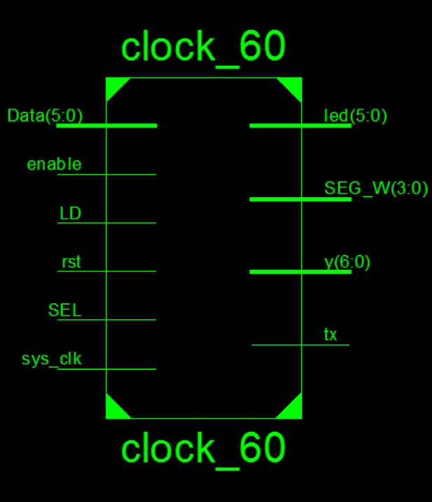
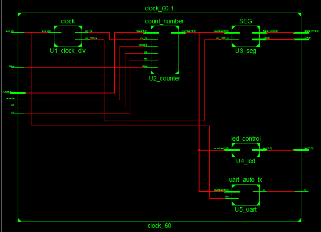
上图为整体顶层视图
这里仅放下数码管显示、计数、时钟分频模块,其他电路过于复杂不宜放入
分析:
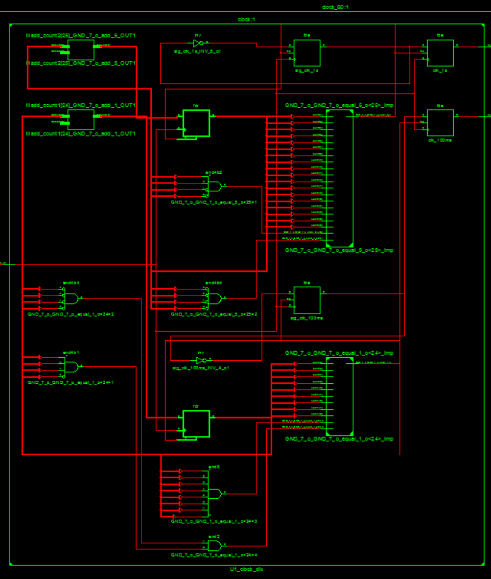
时钟方向:
系统基础时钟经过分频器(clock_div)分为两个频率,clk_1s输出1HZ分频给予计数器。Clk_10ms输出100hz频率给与数码管显示切换刷新。
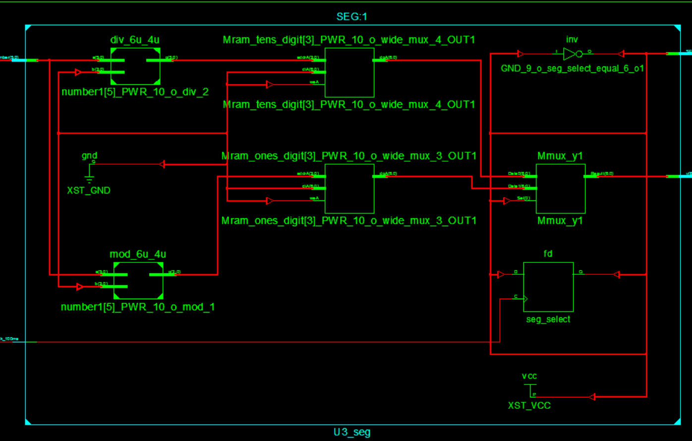
数码管显示方向:
数码管轮询显示模块共有2个4位的输入端,每次clk_10ms时钟信号到来后,该模块都会切换状态,改变数码管的位选,并根据当前数码管的位选选通输入端的信号,并将选通的输入端信号输入7段译码器进行译码,再将译码信号输入数码管,使其显示出对应的数字。
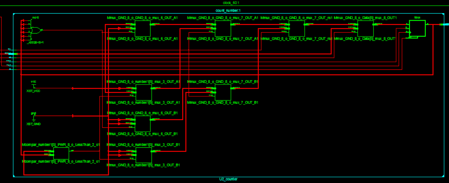
计数器方向:
计数器接入EN,SEL,CLR,LD。首先两者都是接入分频产生的1HZ时钟,EN是总使能开关,控制启停,SEL是选择加法或者减法开关,CLR是异步清零开关。当SEL=1时候,选择加法器计数模式,SEL=0则为减法器。本设计没有采用十进制+六进制的计数器设计方法,而是直接使用6位寄存器进行加减计算。在数码管显示时计算出个位和十位进行显示。计数器的时钟源是开发板时钟源经过分频引出的1Hz时钟信号。
拨码开关方向:
该FPGA开发板上一共有8位的拨码开关,每个拨码开关都有‘1’和‘0’两种状态,因此可以用6位拨码开关以二进制的形式表示0—2^6-1范围内数字,即0-63,满足60进制内任意置数。拨码开关与计数器的置数输入端相连。当按下按键置数按键触发LD=1后,还需要等待一个时钟上升沿的到来(同步置数),数码管上显示的时间会变成用6位拨码开关表示的两位数字。
四、仿真波形图及分析
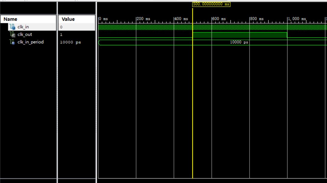 1Hz分频时钟仿真验证
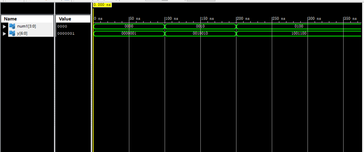
数码管七段译码器仿真
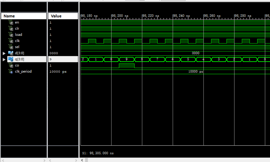
计数器仿真
五、开发板验证及分析
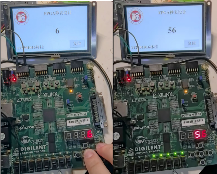
如图,LCD与数码管显示同步,并且每计数10s会自左向右亮起LED灯示意。