ZygoPlanner:一种基于图形的三阶段框架,用于颧骨种植体植入的最佳术前规划|文献速递-医学影像人工智能进展
Title
题目
ZygoPlanner: A three-stage graphics-based framework for optimal preoperative planning of zygomatic implant placement
ZygoPlanner:一种基于图形的三阶段框架,用于颧骨种植体植入的最佳术前规划
01
文献速递介绍
1.1 研究背景 颧骨种植手术是严重上颌骨萎缩患者口腔修复的一种重要治疗选择,它能够避免过度创伤和漫长的骨移植手术流程(阿帕里西奥等人,2014年;罗森施泰因,2020年)。如图1所示,在手术过程中,外科医生通常会将颧骨种植体穿过上颌骨底部植入颧骨,以便进行后续治疗(赫查诺维奇等人,2016年)。具体来说,如果患者图1中的1区、2区和3区出现萎缩,那么在颧骨的每一侧会植入两颗颧骨种植体,这被称为“四种植体法”(达沃和大卫,2019年)。如果只有2区或3区出现萎缩,通常在颧骨的每一侧只植入一颗颧骨种植体,这被称为“经典法”(凯默勒等人,2023年)。 然而,由于种植空间有限且解剖结构复杂,种植体植入位置的任何显著偏差都可能导致继发性创伤或种植体松动,这给牙科临床医生带来了挑战,尤其是在采用“四种植体法”时(鲁埃达和卡塔兰,2023年)。 作为有效缓解上述困境的一种手段,计算机辅助手术技术在颧骨种植手术中得到了广泛应用。其中,手术导航与机器人技术的结合是众多学者关注的领域(陶等人,2022年;吴等人,2022年;拉梅赞扎德等人,2021年;巴莱罗等人,2023年b;范等人,2024年;奥利韦托等人,2023年;佩莱格里诺等人,2020年b;周等人,2021年;鲁埃达等人,2023年;邓等人,2023年;周,2023年)。在这种方法中,外科医生通常会在手术前根据患者的CT扫描结果预先规划种植路径。然后,在手术过程中,他们在手术导航或机器人的辅助下沿着规划好的路径进行种植,以确保达到预期的治疗效果(蓬努萨米和米洛罗,2020年;里戈等人,2021年)。目前,在导航或机器人辅助下的术中种植体植入精度已达到毫米级别(巴莱罗等人,2023年a;范等人,2023年),这也对术前规划的有效性提出了更高的标准。 然而,尽管术前规划是术中导航的重要准备工作,但颧骨种植的术前规划尚未取得重大突破,临床上大多仍依赖通过商业医疗软件进行人工设计(莫罗等人,2022年;里纳尔迪和甘兹,2019年;邢等人,2021年)。人工术前规划要求外科医生在患者的术前CT扫描图像上仔细确定种植路径的起点和终点,确保每条种植路径的终点落在颧骨内,并且路径不会穿透眼眶壁或颞窝等关键区域(艾哈迈德等人,2020年;阿帕里西奥等人,2021年)。同时,这些路径还应达到最佳治疗效果,而如何客观量化这种效果也仍然存在争议(拉马尔 - 桑切斯等人,2023年)。此外,不同外科医生规划的结果可能存在显著差异,而且人工规划无法保证获得最佳的种植轨迹。实际上,确定患者种植路径的起点取决于解剖结构。由于接受颧骨种植手术的患者通常上颌骨严重萎缩,牙槽骨大量吸收,颧骨种植体的起点通常放置在腭侧,以实现四皮质骨的稳定(洪等人,2017年)。这一操作相对容易通过人工完成,而真正的挑战在于确定终点以达到上述效果(森特内罗等人,2018年)。在我们开展这项研究之前,关于确定种植轨迹最佳终点的研究尚未取得令人满意的效果,因此这仍然是解决颧骨种植自动规划问题的主要挑战,目前许多研究也仍然更多地聚焦于此(郭等人,2023年;萨纳维亚等人,2023年;沃瑟尔曼等人,2022年;顾等人,2023年;洛鲁索等人,2021年)。因此,为了克服上述规划过程中耗时、耗力、依赖经验且可重复性差的局限性,颧骨种植的自动术前规划具有重要意义。 ### 1.2 相关研究 据我们所知,目前仍然缺乏一种自动、完整、端到端的解决方案,涵盖颧骨的分割以及颧骨种植最佳路径的生成。 就当前的技术水平而言,郭等人(2023年)引入了一种虚拟设计算法,旨在通过术前规划软件(IVSP Image)确定性能最佳的种植路径。然而,他们的方法仍然局限于“经典法”种植,并且他们的最佳轨迹仅仅是从颧骨的枚举三角形顶点中选择的,这在个性化案例中提升种植效果方面仍有很大的潜力可挖。此外,该方法没有明确说明如何添加种植约束条件,或者是否能够自动实现。规划过程仍然需要一些人工干预,即确定起点和颧骨定位,这凸显了该系统在进一步实现自动化和精确化方面的需求。其他研究仍然高度依赖人工操作(萨纳维亚等人,2023年;沃瑟尔曼等人,2022年;蓬努萨米和米洛罗,2020年)。 在子任务方面,已经有一些有见地的研究。对于颧骨的分割,陶等人(2023年a)在卷积神经网络中添加了边缘监督模块,以便更专注于颧骨的轮廓,实现了对颧骨的精确分割。森田等人(2023年)利用U型网络将面骨自动分割为包括颧骨在内的八个区域,这有助于虚拟手术规划。张等人(2023年)开发了一种无偏热图编码方法,使分割框架受益,并能够准确提取颧骨。陶等人(2023年b)提出了一个两阶段网络来检测颧骨上的标志点,在我们的研究场景中,这也能够定位有效的规划区域。然而,上述研究都基于深度学习方法。由于深度学习模型缺乏可解释性是一个普遍的局限性,因此仍需要进一步验证这些模型在不同医院数据集上的可迁移性。同时,这些基于学习的方法对硬件的计算性能也有很高的要求。 对于最佳种植路径的生成,骨 - 种植体接触(BIC)是评估种植体固定效果的关键指标,因为较大的BIC通常意味着更好的固定效果,从而使治疗成功率更高(埃林森等人,2004年;特里西等人,2015年)。因此,最大化BIC已成为许多研究的共同追求(许等人,2017年;郭等人,2023年;洛鲁索等人,2021年)。为了自动获得最佳种植路径,主要存在两个挑战,即量化BIC以及确定能使BIC最大化的路径。为了解决这个问题,顾等人(2023年)开发了一种基于三维图像配准和分割的BIC量化技术。周等人(2020年)利用生物力学分析来量化BIC与种植体负荷之间的关系。佩莱格里诺等人(2020年a)基于解剖标志点和CT扫描,考虑性别、种植体类型和轨迹之间的差异以及它们对骨结合和窦内路径的影响,评估了颧骨种植的颧骨可用性并确定了最佳轨迹。尽管上述计算机辅助手术技术提供了一些思路,但它们无法自动高效地生成最佳种植路径,在关键步骤上仍然依赖人工操作,在该领域仍有很大的进一步研究和改进空间。 ### 1.3 研究贡献 基于上述背景,本研究将提出ZygoPlanner,这是一个高效的颧骨种植术前规划框架。它能够对颧骨种植中的医学指标和临床约束进行基于图形的数学量化,且不依赖任何基于学习的方法。外科医生只需花费几秒钟在患者的三维颅骨模型上点击种植起点,ZygoPlanner就会自动高效地生成最佳种植路径。具体而言,为了克服可解释的颧骨定位这一挑战,我们基于患者颅骨的几何特征构建了一个统计多平面切割模型。利用患者颅骨近似的左右对称性,我们估计模型的对称平面,并自动提取颧骨周围的有效规划点云。为了克服生成最佳种植路径的挑战,我们首先提出了一种适用于凹面几何形状的忠实于表面的点云填充算法,以便在不破坏颧骨原始表面的情况下在规划区域内获得密集的点。然后,我们以种植中心为光源建立辐射场,并提取密集光锥内的分区背光点作为替代种植终点,以生成密集的替代路径。最后,我们以图形化的方式整合了颧骨种植中的医学概念。我们创新性地利用沿三维路径位于种植体表面层内的有效规划点云的密度,实现了医学BIC的图形化表示。基于这种表示,可以在多种约束条件下获得最佳路径。 本研究的主要贡献可总结如下: 1. 我们开发了一种无需训练的、可解释的图形化方法,利用患者三维颅骨的形状先验知识实现高效的颧骨定位; 2. 我们提出了一种适用于某些凹面几何形状的忠实于表面的点云填充算法,能够在仔细保留表面完整性的同时在颧骨内填充密集的点,有助于生成密集的替代路径; 3. 我们通过分析沿三维路径位于种植体表面层内的有效规划点云的密度,实现了医学BIC的图形化表示,从而在多种约束条件下获得最佳路径。 我们提出的ZygoPlanner框架可能是首个将颧骨定位、替代路径生成以及最佳种植路径计算无缝集成的颧骨种植规划流程,旨在减轻外科医生传统上繁琐的手术规划过程。
Abatract
摘要
Zygomatic implant surgery is an essential treatment option of oral rehabilitation for patients with severemaxillary defect, and preoperative planning is an important approach to enhance the surgical outcomes.However, the current planning still heavily relies on manual interventions, which is labor-intensive, experiencedependent, and poorly reproducible. Therefore, we propose ZygoPlanner, a pioneering efficient preoperativeplanning framework for zygomatic implantation, which may be the first solution that seamlessly involvesthe positioning of zygomatic bones, the generation of alternative paths, and the computation of optimalimplantation paths. To efficiently achieve robust planning, we developed a graphics-based interpretable methodfor zygomatic bone positioning leveraging the shape prior knowledge. Meanwhile, a surface-faithful pointcloud filling algorithm that works for concave geometries was proposed to populate dense points within thezygomatic bones, facilitating generation of alternative paths. Finally, we innovatively realized a graphicalrepresentation of the medical bone-to-implant contact to obtain the optimal results under multiple constraints.Clinical experiments confirmed the superiority of our framework across different scenarios.
颧骨种植手术是严重上颌骨缺损患者口腔修复的一种重要治疗选择,而术前规划是提高手术效果的重要途径。然而,目前的规划仍然在很大程度上依赖人工干预,这既耗费人力,又取决于经验,而且可重复性较差。因此,我们提出了ZygoPlanner,这是一种开创性的、高效的颧骨种植术前规划框架,它可能是首个无缝涉及颧骨定位、替代路径生成以及最佳种植路径计算的解决方案。 为了高效地实现可靠的规划,我们利用形状先验知识开发了一种基于图形的、可解释的颧骨定位方法。同时,我们提出了一种适用于凹面几何形状的忠实于表面的点云填充算法,用于在颧骨内填充密集的点,从而有助于生成替代路径。最后,我们创新性地实现了医学上骨与种植体接触情况的图形化表示,以便在多种约束条件下获得最佳结果。 临床实验证实了我们的框架在不同场景下的优越性。
Method
方法
Fig. 2 illustrates the overview of our proposed ZygoPlanner framework. To produce clinically compliant planning outcomes, users needto select the implantation entry points at the surface of the maxillaryon the 3D skull reconstructed from the patient’s CT scans, which isrelatively easy (Centenero et al., 2018). Utilizing these points alongwith the 3D model as inputs, our framework undergoes a three-stageprocess to generate optimal implantation trajectories. Stage 𝐼 involvesthe automatic localization of the zygomatic bones on both sides of theskull using shape prior knowledge, which includes cranial symmetryplane estimation, maxillary separation, and zygomatic bone positioning. Stage 𝐼𝐼 first performs surface-faithful filling of the non-convexzygomatic point cloud. It then establishes a radiation field with theimplantation center as the light source and extracts the zoned ‘backlit’ points in dense light cones as alternative implantation endpoints.Stage 𝐼𝐼𝐼 introduces multiple constraints and maximizes the graphicalrepresentation of BIC for the greatest implantation firmness to obtainthe optimal implanted paths.
图2展示了我们所提出的ZygoPlanner框架的概述。为了生成符合临床要求的规划结果,用户需要在根据患者CT扫描重建的三维颅骨上的上颌骨表面选择种植起点,这相对比较容易(森特内罗等人,2018年)。利用这些点以及三维模型作为输入,我们的框架经过三个阶段的流程来生成最佳的种植轨迹。 第一阶段(阶段𝐼)涉及利用形状先验知识对颅骨两侧的颧骨进行自动定位,这包括颅骨对称平面估计、上颌骨分离以及颧骨定位。 第二阶段(阶段𝐼𝐼)首先对非凸的颧骨点云进行忠实于表面的填充。然后以种植中心为光源建立一个辐射场,并提取密集光锥内分区的“背光”点作为替代种植终点。 第三阶段(阶段𝐼𝐼𝐼)引入多种约束条件,并最大化骨 - 种植体接触(BIC)的图形化表示,以实现最大的种植稳固性,从而获得最佳的种植路径。
Conclusion
结论
In this work, we presented an efficient graphics-based zygomaticimplantation planning framework, achieving a graphical mathematical quantification of medical indicators and clinical constraints inzygomatic implantation. Experimental results demonstrate that ourmethod achieves superior performance in both precision and efficiency,outperforming other methods or manual planning by a considerablemargin. It will significantly facilitate computer-assisted zygomatic implant surgery, bringing considerable benefits to both clinical zygomaticimplant surgeons and patients. More clinical data will be collected toverify the stability and improve the detailed design of the frameworkin the future.
在这项工作中,我们提出了一个高效的基于图形学的颧骨种植手术规划框架,实现了对颧骨种植手术中医疗指标和临床约束条件的图形化数学量化。实验结果表明,我们的方法在精度和效率两方面都取得了卓越的性能,在很大程度上优于其他方法或人工规划。这将极大地推动计算机辅助颧骨种植手术的发展,为临床颧骨种植外科医生和患者都带来显著的益处。未来,我们将收集更多的临床数据,以验证该框架的稳定性并改进其细节设计。
Figure
图
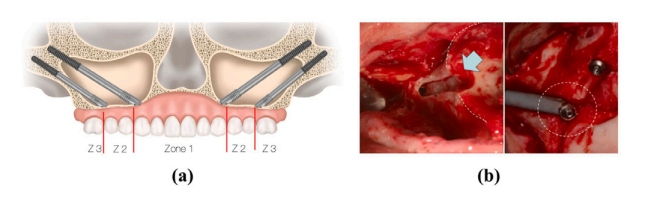
Fig. 1. (a) and (b) depict the virtual and actual schematics of zygomatic implantation,respectively (Bedrossian et al., 2023).
图1:(a)和(b)分别描绘了颧骨种植的虚拟示意图和实际示意图(贝德罗斯ian等人,2023年)。
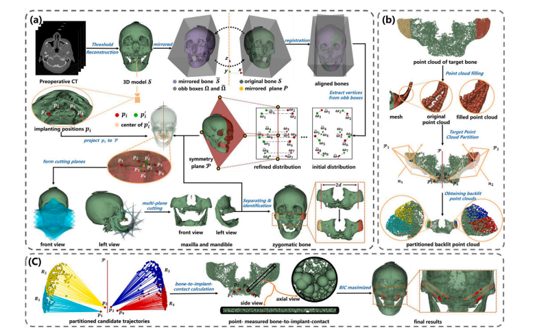
Fig. 2. The overview of our pipeline comprises three stages: (a) automatic zygomatic bone positioning through shape-prior-knowledge-based multi-planar cutting. (b) Generationof partitioned alternative trajectories guided by extracting dense ‘backlit’ points. (c) Utilization of a BIC-maximized algorithm to determine the optimal implanted paths.
图2:我们的流程概述包含三个阶段:(a) 通过基于形状先验知识的多平面切割实现颧骨的自动定位。(b) 在提取密集 “背光” 点的引导下生成分区的替代轨迹。(c) 利用骨 - 种植体接触(BIC)最大化算法来确定最佳的种植路径。
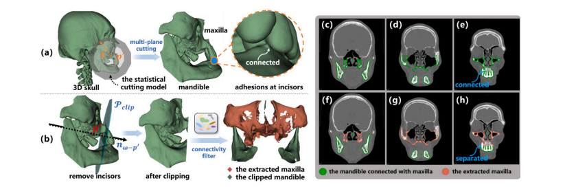
Fig. 3. (a) Adhesions occur at incisors, which connects the maxilla and mandible, leading to the failure of the connectivity filter; (b) Rectify the model by clipping the region toprevent potential adhesions. (c–e) The failure of the connectivity filter on the original model. (f–h) Successful to extract the maxilla after automatically removing incisors
图3:(a) 粘连出现在连接上颌骨和下颌骨的门牙处,导致连通性滤波器失效;(b) 通过裁剪该区域来修正模型,以防止潜在的粘连情况。(c–e) 连通性滤波器在原始模型上失效的情况。(f–h) 在自动移除门牙后成功提取出了上颌骨。
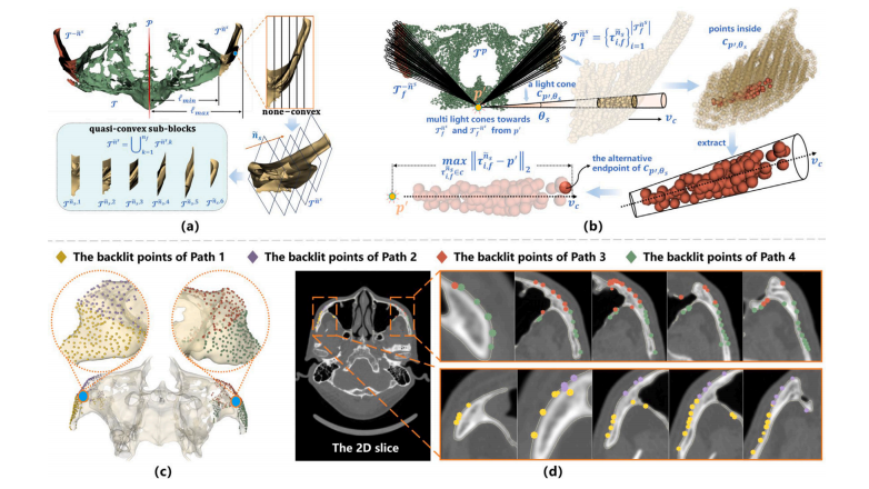
Fig. 4. (a) To facilitate point cloud filling, the zygomatic bone is partitioned into quasi-convex sub-blocks via multi-plane cutting. (b) Construct a radiative field with 𝑝 ′ as thelight source to generate dense light cones with an angle 𝜃𝑠 , pointing towards the zygomatic bones ̃𝑛 𝑠 and then compute the backlit point in each light cone as the endpoint ofalternative paths. (c–d) The extracted backlit points of different paths in 3D models and 2D slices after point cloud filling
图4:(a) 为了便于进行点云填充,通过多平面切割将颧骨分割成近似凸形的子块。(b) 以𝑝 ′ 为光源构建一个辐射场,生成角度为𝜃**𝑠 的密集光锥,这些光锥指向颧骨 ̃𝑛 𝑠 ,然后计算每个光锥内的背光点,将其作为替代路径的终点。(c–d) 在点云填充后,三维模型和二维切片中不同路径所提取出的背光点。
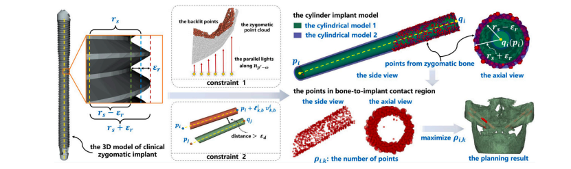
Fig. 5. The BIC index is represented by the number of points between cylindrical model 1 and cylindrical model 2, denoted as 𝜌𝑖,𝑘. And the optimal path is generated by maximizing𝜌𝑖,𝑘 under multiple constraints
图5:骨-种植体接触(BIC)指标由圆柱模型1和圆柱模型2之间的点数表示,记为(\rho{i,k})。并且,最佳路径是通过在多种约束条件下使(\rho{i,k})最大化而生成的。

Fig. 6. (a) Biomarkers 𝑚1 , 𝑚2 , and 𝑚3 respectively denote the distal zygomatic body, the distal zygomatic arch, and the distal frontal process. The cylindrical cutting model, withradius , should encompass 𝑚1 while excluding 𝑚2 and 𝑚3 . An optimal planning distance 𝑑 should establish a clipping plane positioned between 1 and 2 at the terminationpoint of the zygomaticomaxillary suture (ZM suture). (b) The success rate of multi-plane cutting with different according to the criteria in (a). (c) The success rate of clippingwith different 𝑑 according to the criteria in (a).
图6:(a) 生物标志物(m_1)、(m_2)和(m_3)分别表示颧骨体远端、颧弓远端和额突远端。半径为(\mathcal{L})的圆柱切割模型应包含(m_1),同时排除(m_2)和(m_3)。在颧上颌缝(ZM缝)的终止点处,应在平面(\mathcal{P}1)和平面(\mathcal{P}2)之间设置一个最佳规划距离(d)来确定一个切割平面。(b) 根据(a)中的标准,不同(\mathcal{L})值下多平面切割的成功率。(c) 根据(a)中的标准,不同(d)值下切割的成功率。
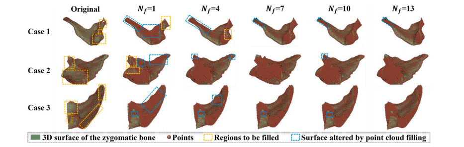
Fig. 7. The point cloud filling results with different 𝑁𝑓 on 3 random cases while 𝑅𝑓 = 10. The underfilled regions of the zygomatic point cloud and the damaged areas on thesurface are circled in orange and blue boxes, respectively
图7:在(R_f = 10)的情况下,对3个随机案例采用不同的(N_f)值所得到的点云填充结果。颧骨点云未充分填充的区域和表面受损区域分别用橙色框和蓝色框圈出。
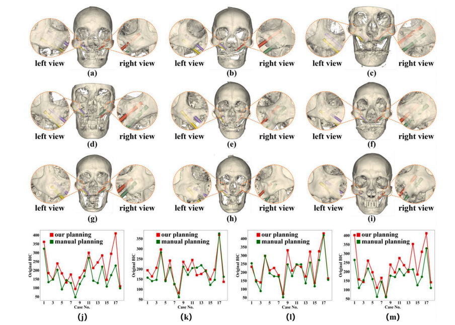
Fig. 8. (a–i) present the qualitative implantation planning results from 9 cases by our method. (j–m) respectively plot the original BIC of 𝑃1 -𝑃4 in 18 cases between our planningresults and those of manual planning
图8:(a–i) 展示了使用我们的方法对9个案例进行的定性种植规划结果。(j–m) 分别绘制了18个案例中,我们的规划结果与人工规划结果之间,(P_1)至(P_4)的原始骨 - 种植体接触(BIC)情况。
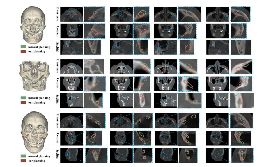
Fig. 9. The qualitative results of our planned paths and the manually planned paths on the 2D slices in 3 cases.
图9:在3个案例中,我们规划的路径与人工规划的路径在二维切片上的定性结果。
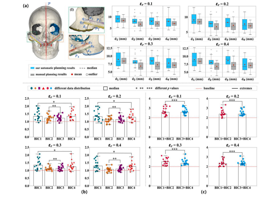
Fig. 10. (a) Comparison of 𝑑1 to 𝑑4 between our planning results and manual results by expert surgeons with different 𝜀𝑟 , where 𝑑1 -𝑑4 denotes the distance from the implantpaths 𝑃1 -𝑃4 to either the infraorbital margin or the lower zygomatic bone edge. (b) The relative BIC of path 1 to path 4 planned by our method compared with the correspondingmanual design, denoted as BIC1 to BIC4. (c) The relative overall BIC in the left or right zygomatic bone with different 𝜀?
图10:(a)在不同的(\varepsilon_r)值下,我们的规划结果与专家外科医生的人工规划结果之间关于(d_1)到(d_4)的比较,其中(d_1)至(d_4)表示从种植路径(P_1)至(P_4)到眶下缘或颧骨下缘的距离。(b)我们的方法规划的路径1到路径4的相对骨-种植体接触(BIC)与相应的人工设计的比较,记为(BIC_1)到(BIC_4)。(c)在不同的(\varepsilon_{?})值下,左右颧骨的相对总体骨-种植体接触(BIC)情况。
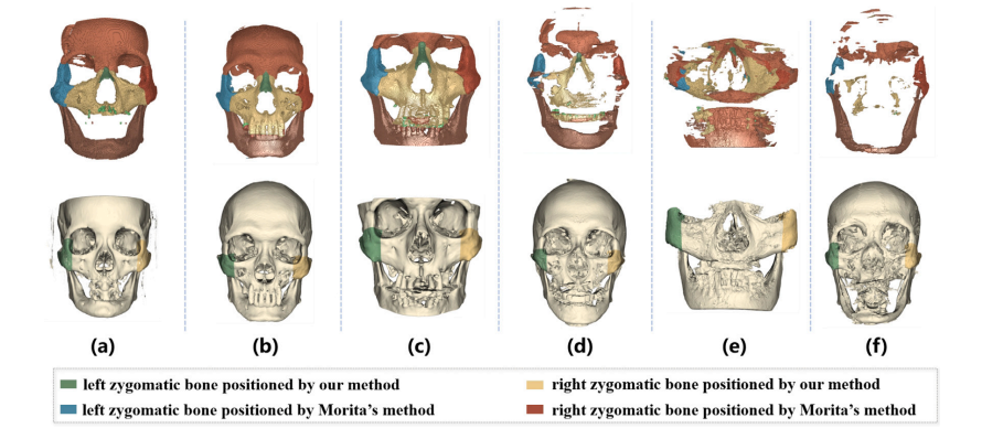
Fig. 11. Visualization of Zygomatic Bone Positioning on six random cases: results in the first row were obtained following Morita et al. (2023), while those in the second rowwere from our ZygoPlanner. Notably, (e) is from the CT scan performed on a plaster model.
图11:六个随机案例的颧骨定位可视化结果:第一行的结果是依据森田等人(2023年)的方法得到的,而第二行的结果则来自我们的ZygoPlanner。值得注意的是,(e) 是对一个石膏模型进行CT扫描后得到的结果。
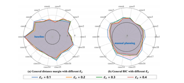
Fig. 12. The general distance margin and general BIC with different 𝜀𝑟 in all cases.
图12:在所有案例中,不同的(\varepsilon_r)值所对应的一般距离裕度以及一般的骨-种植体接触(BIC)情况。
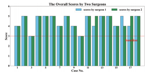
Fig. 13. The case-wise overall score of the Likert rating scale survey
图13:利克特量表评分调查的按案例的总体得分情况
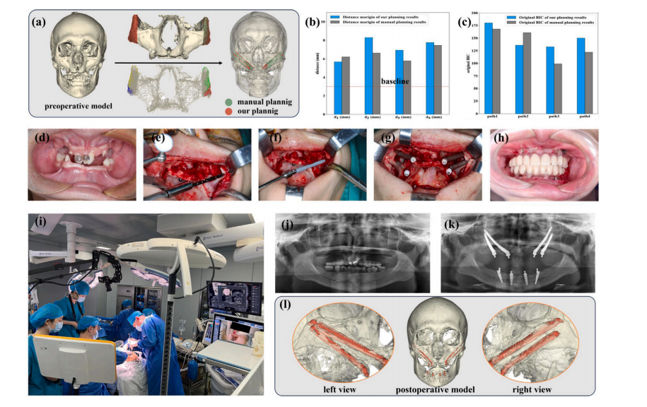
Fig. 14. The clinical feasibility evaluation. (a) The preoperative planning for a clinical case was conducted via our ZygoPlanner and manual planning. The positioning of thezygomatic bones and the partitioning backlit points in our framework are also demonstrated. (b–c) The comparison in 𝑑1 to 𝑑4 and the original BIC of different paths, where theZygoPlanner adopted the parameters: = 50, 𝑑 = 42, 𝑁𝑓 = 7, 𝜃𝑠 = 1.5, 𝑅𝑓 = 10, 𝜀𝑟 = 0.2 and 𝑟𝑠 = 2. (d–h) The surgical procedure, where d denotes the preoperative result andh denotes the postoperative effect with dentures. (i) Schematic diagram of the surgical scene, with the surgeon completing the zygomatic implant under the guidance of surgicalnavigation. (j) The preoperative panoramic image. (k) The postoperative panoramic image. (l) 3d model reconstructive from postoperative CT scans.
图14:临床可行性评估。(a) 通过我们的ZygoPlanner和人工规划对一个临床病例进行术前规划。同时也展示了我们的框架中颧骨的定位以及分区背光点。(b–c) 对(d_1)至(d_4)的比较以及不同路径的原始骨-种植体接触(BIC)情况,其中ZygoPlanner采用的参数为:(\mathcal{L} = 50),(d = 42),(N_f = 7),(\theta_s = 1.5),(R_f = 10),(\varepsilon_r = 0.2) 以及 (r_s = 2)。(d–h) 手术过程,其中d表示术前结果,h表示安装假牙后的术后效果。(i) 手术场景示意图,外科医生在手术导航的引导下完成颧骨种植。(j) 术前全景图像。(k) 术后全景图像。(l) 由术后CT扫描重建的三维模型。
Table
表
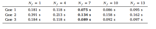
Table 1Comparison of the time consuming with different 𝑁𝑓 in point cloud filling of 3cases
表1 3个案例中点云填充时不同(N_f)值的耗时比较
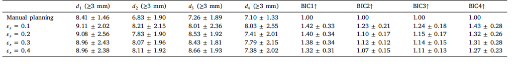
Table 2Quantitative comparison of the manual planning and our automatic planning with different 𝜀𝑟 on 𝑑1 to 𝑑4 and BIC1 to BIC4
表2 人工规划与我们的自动规划在不同(\varepsilon_r)值下,针对(d_1)至(d_4)以及(BIC_1)至(BIC_4)的定量比较
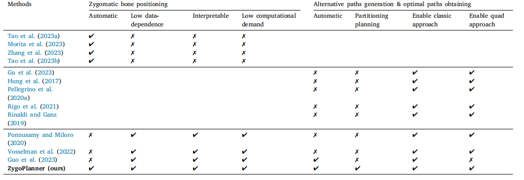
Table 3Qualitative comparative analysis with other methods
表3 与其他方法的定性对比分析
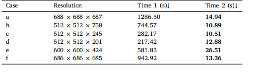
Table 4Time cost comparison of zygomatic bone positioning between (Morita et al., 2023)(Time 1) and our method (Time 2) on six cases
表4 在六个案例上,(森田等人,2023年)的方法(时间1)与我们的方法(时间2)在颧骨定位方面的时间成本比较
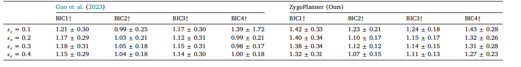
Table 5Quantitative comparison of state of the art method and ours with different 𝜀𝑟 on BIC1 to BIC4
表5 在不同的(\varepsilon_r)值下,当前最先进的方法与我们的方法在(BIC_1)至(BIC_4)方面的定量比较
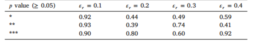
Table 6The 𝑝-value of BIC to verify the consistency of the left and right implantation effects
表6 用于验证左右植入效果一致性的骨 - 种植体接触(BIC)的p值
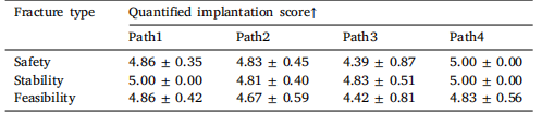
Table 7Quantified path-wise results of the likert rating scale survey
表7 利克特量表评分调查的分路径量化结果