STM32超声波模块
一:超声波模块
1:工作原理
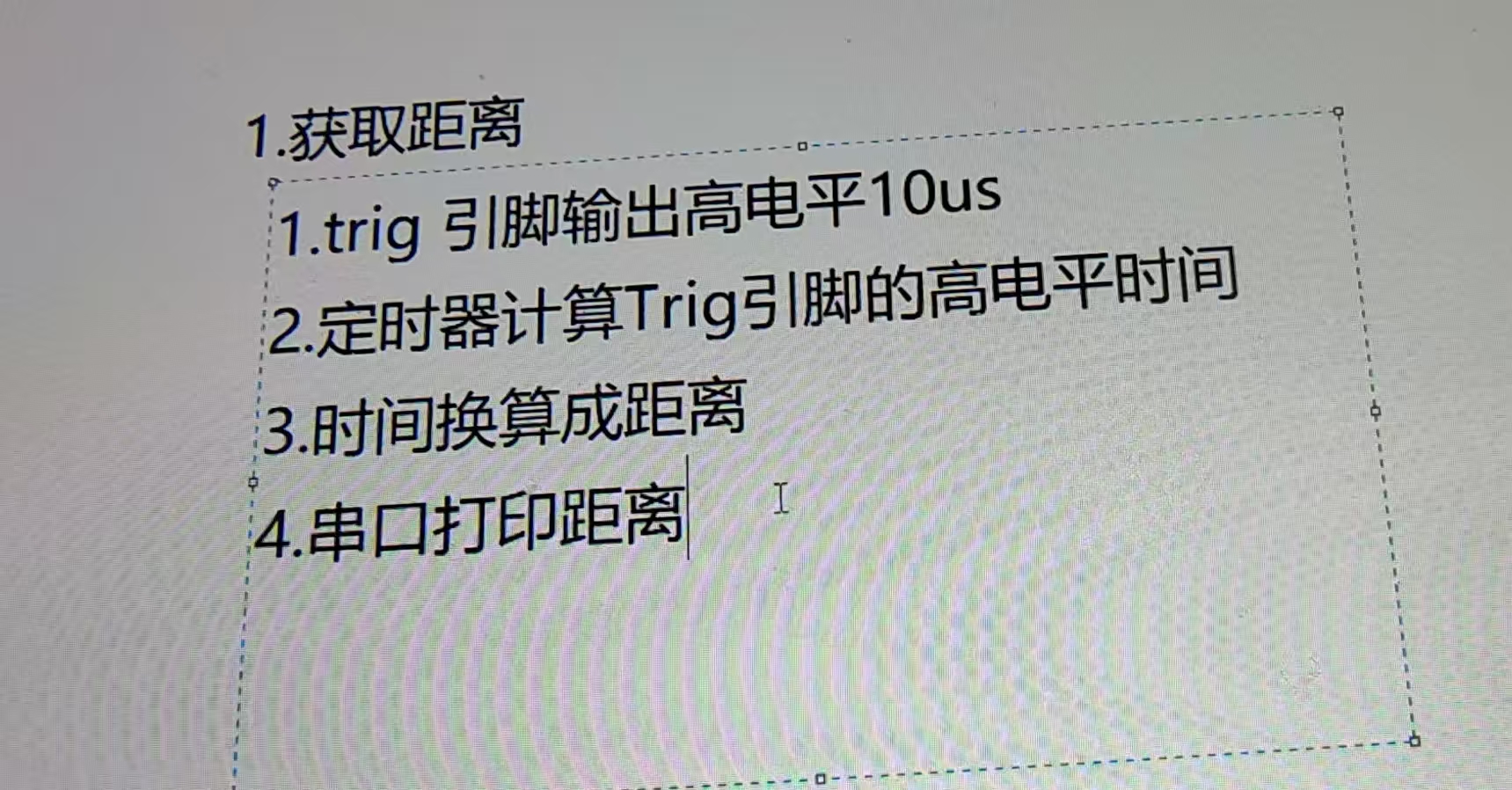
采用IO触发测距,给至少10us的高电平信号。
模块自动发送8个40KHz的方波,自动检测是否有信号返回。
·有信号返回,通过IO输出一高电平,高电平持续时间就是超声波从发射到返回的时间声波从发射到返回的时间
· HC-SRO4超声波测距模块提供2cm-400cm的测距功能,精度达3mm。
2.硬件接线
四根杜邦线,VCC连接单片机3.3-5V (推荐5V供电),GND接到板子的GND, Trig 为外部触发信号输入,输入一个10us的高电平即可触发模块测距,Echo即为 回响信号输出,测距结束时此管引脚输出一个低电平,电平宽度反映超声主返时间之和。 3.控制超声波测距步骤
初始化超声波引脚和定时器时钟· 初始化引脚模式和定时器中断
Tim.c
#include "stm32f10x.h"
#include "Tim.h"uint16_t  mountus;void delay_us(uint32_t us)
{us *=8;while(us--);}void delay_ms(uint32_t ms)
{while(ms--){delay_us(1000);}}void Base_Tim_Init(void)
{TIM_TimeBaseInitTypeDef TIM_TimeBaseInitstruct;NVIC_InitTypeDef NVIC_Initstruct;RCC_APB1PeriphClockCmd(RCC_APB1Periph_TIM2,ENABLE);NVIC_PriorityGroupConfig(NVIC_PriorityGroup_2);TIM_TimeBaseInitstruct.TIM_ClockDivision=TIM_CKD_DIV1;TIM_TimeBaseInitstruct.TIM_CounterMode=TIM_CounterMode_Up ;TIM_TimeBaseInitstruct.TIM_Period=1000-1;TIM_TimeBaseInitstruct.TIM_Prescaler=72-1;TIM_TimeBaseInitstruct.TIM_RepetitionCounter=0;TIM_TimeBaseInit( TIM2, &TIM_TimeBaseInitstruct);TIM_ITConfig( TIM2, TIM_IT_Update, ENABLE);TIM_Cmd(TIM2, DISABLE);NVIC_Initstruct.NVIC_IRQChannel=TIM2_IRQn ;NVIC_Initstruct.NVIC_IRQChannelPreemptionPriority=0;NVIC_Initstruct.NVIC_IRQChannelSubPriority=0;NVIC_Initstruct.NVIC_IRQChannelCmd=ENABLE;NVIC_Init(&NVIC_Initstruct);}void HC04_Init()
{GPIO_InitTypeDef GPIO_Initstruct;RCC_APB2PeriphClockCmd( RCC_APB2Periph_GPIOB,ENABLE);GPIO_Initstruct.GPIO_Pin= GPIO_Pin_11;GPIO_Initstruct.GPIO_Mode=GPIO_Mode_Out_PP;GPIO_Initstruct.GPIO_Speed=GPIO_Speed_10MHz;GPIO_Init( GPIOB, &GPIO_Initstruct);GPIO_Initstruct.GPIO_Pin=GPIO_Pin_10;GPIO_Initstruct.GPIO_Mode=  GPIO_Mode_IPD;GPIO_Init( GPIOB, &GPIO_Initstruct);}void open_Tim()
{mountus=0;TIM_SetCounter( TIM2,0);TIM_Cmd(TIM2, ENABLE);}void close_Tim()
{TIM_Cmd(TIM2, DISABLE);}void TIM2_IRQHandler ()
{if(TIM_GetITStatus(TIM2, TIM_IT_Update) != RESET){mountus++;TIM_ClearITPendingBit(TIM2, TIM_IT_Update);}}int Get_Echo_Time()
{uint16_t t=0;t=mountus*1000;t=t+TIM_GetCounter(TIM2);TIM_SetCounter( TIM2,0);delay_ms(50);return t;}float Get_Length()
{int i=0;float sum=0;uint16_t t=0;float length=0;while(i<5){	GPIO_SetBits(GPIOB,GPIO_Pin_11);delay_us(20);GPIO_ResetBits(GPIOB,GPIO_Pin_11);while(GPIO_ReadInputDataBit(GPIOB,GPIO_Pin_10) == RESET );open_Tim();i++;while(GPIO_ReadInputDataBit(GPIOB,GPIO_Pin_10) == SET );close_Tim();t=Get_Echo_Time();length=((float)t/58.0);sum=sum+length;}length=sum/5.0;return length;}
Tim.h
#ifndef _TIM_H_
#define _TIM_H_void Base_Tim_Init(void);
void HC04_Init(void);
float Get_Length(void);#endif
main.c
#include "stm32f10x.h"
#include "main.h"
#include "led.h"
#include "Bear.h"
#include "key.h"
#include "relay.h"
#include "shake.h"
#include "wireless.h"
#include "exti_key.h"
#include "usart.h"
#include "stdio.h"
#include "Tim.h"void delay(uint16_t time)//延时1ms  软件延时粗延时
{uint16_t i=0;while(time --){i=12000;while(i --);}}int  main()
{float length=0;LED_Init();Base_Tim_Init();HC04_Init();my_usart_Init();while(1){length = Get_Length();printf("%lf\r\n",length );}}
代码心得
1:
定时器中断工作机制
定时器配置:
在您的代码中,TIM2配置为1MHz计数频率(72MHz主频/72分频)
自动重装载值1000 → 每1ms(1000μs)产生一次更新中断
每1ms触发一次中断,与高电平持续时间无关
中断频率由定时器配置决定,不是由外部信号决定
2
为什么需要延迟?
1:
void TIM_SetCounter(TIM_TypeDef* TIMx, uint16_t Counter)
{/* Check the parameters */assert_param(IS_TIM_ALL_PERIPH(TIMx));/* Set the Counter Register value */TIMx->CNT = Counter;
}
实际上这个函数是对一个寄存器进行了赋值,所以我们需要一定的时间去让寄存器赋值,这个就是他的作用,我们这里用了50ms,就是充分让 寄存器赋值 这个步骤可以完成!
在原始代码中:
c
int Get_Echo_Time() {t = mountus*1000 + TIM_GetCounter(TIM2);TIM_SetCounter(TIM2,0);delay_ms(50);  // 关键延迟return t;
}
这个延迟解决了两个问题:
传感器恢复时间:
HC-SR04需要50-60ms的恢复周期
连续测量会导致传感器无法响应
中断冲突预防:
重置定时器(
TIM_SetCounter(0))和mountus=0操作需要时间无延迟时,下次测量可能打断重置过程
3总结代码
定时器中断由定时器硬件触发,与Echo引脚状态无关
mountus记录的是时间流逝(每1ms增加),不是信号事件高电平期间定时器持续运行,通过:
中断次数(
mountus) → 完整毫秒数当前计数值 → 亚毫秒时间
延迟50ms解决了传感器恢复和操作原子性问题
最佳实践:用中断保护替代延迟,并在主循环中管理传感器时序
1. 基本概念对比
| 数据类型 | 符号 | 位宽 | 范围 | 头文件 |
|---|---|---|---|---|
int | 有符号 | 32位 | -2,147,483,648 到 2,147,483,647 | 内置 |
uint16_t | 无符号 | 16位 | 0 到 65,535 | #include <stdint.h> |
uint32_t | 无符号 | 32位 | 0 到 4,294,967,295 | #include <stdint.h> |