【QGIS二次开发】地图编辑-04
系列目录:
【QGIS二次开发】地图显示与交互-01_qgis二次开发加载地图案例-CSDN博客
【QGIS二次开发】地图显示与交互-02_setlayerlabeling-CSDN博客
【QGIS二次开发】地图符号与色表-03-CSDN博客
4 地图编辑
4.1 添加点要素
功能演示:
运行程序后,点击菜单栏中的“数据->添加矢量数据”以导入测试所需的点要素矢量图层。
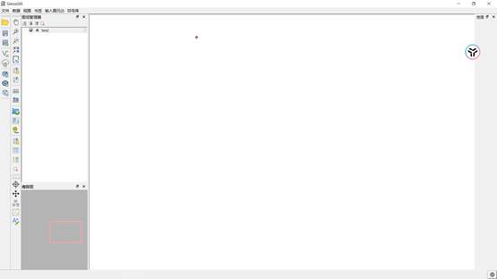
图 30 导入数据示意图
在图层列表中选中相应的图层,然后单击右侧边栏中的“启动/关闭几何编辑”按钮,以启动编辑模式。接着,点击“添加点”按钮,进入点添加模式。此时,利用鼠标左键在图框内的任意位置进行点击,将弹出一个窗口,用于设置新增点要素的属性值。
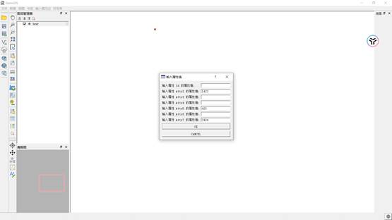
图 31 为新要素添加属性示意图
在属性值编辑窗口中,可以根据需要填写新增点要素的属性信息。这些属性值默认为Null,但可以选择全部填入或者部分填入,根据实际情况进行设置,也可以通过点击“Cancel”按钮取消添加。
添加完成后,新的点要素将在图层和属性表中显示出来。
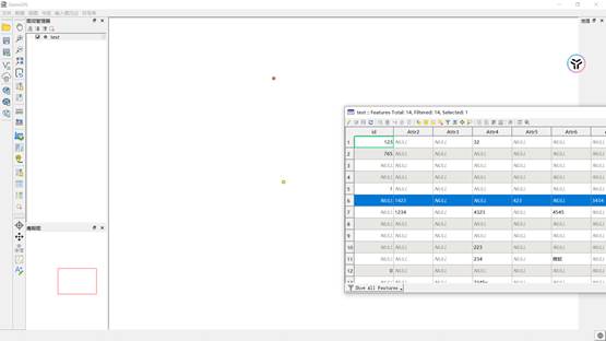
图 32 添加完成后的新要素及其属性展示
从上图可以看到,添加的点要素成功录入并显示在图层和属性表中。
代码展示:
定义了一个名为QgsMapToolEditPoint的类,继承自QgsMapTool用来处理地图编辑操作。构造函数接受一个QgsMapCanvas和QgsVectorLayer,分别表示地图画布和当前图层。
在重载的鼠标按下事件函数canvasPressEvent中,首先检查当前图层是否有效,然后获取鼠标点击位置的坐标。然后启动图层编辑模式,通过addFeature方法创建新的点要素,并通过用户界面弹出窗口(QDialog)收集用户输入的属性值。用户可以为每个属性输入相应的数值或文本,并通过OK按钮确认。
用户在点击OK按钮后,程序会将用户输入的属性值与字段进行匹配,并添加新的要素至图层。如果用户点击Cancel按钮,则取消编辑操作,删除刚刚添加的要素。整个过程通过连接信号槽机制实现,其中包括了用户输入校验、属性值转换以及图层刷新等步骤。核心代码如下:
QgsMapToolEditPoint::QgsMapToolEditPoint(QgsMapCanvas* mapcanvas, QgsVectorLayer* currentlayer) : QgsMapTool(mapcanvas), m_mapCanvas(mapcanvas), m_currentLayer(currentlayer)
{  m_mapCanvas = mapcanvas;  m_currentLayer = currentlayer;
}  QgsMapToolEditPoint::~QgsMapToolEditPoint() {};  void  QgsMapToolEditPoint::canvasPressEvent(QgsMapMouseEvent* e) {  if (!m_currentLayer)  {  // 处理图层无效的情况  return;  }  // 从函数体内获取点击的点坐标  QgsMapCanvas* canvas = this->canvas();  if (!canvas)  {  // 处理无效的画布  return;  }  QgsPointXY point = canvas->getCoordinateTransform()->toMapCoordinates(canvas->mouseLastXY());  m_currentLayer->startEditing();  QgsFeature feature;  // 创建新要素,传递用户点击的点坐标  feature.setGeometry(QgsGeometry::fromPointXY(point));  QgsFields fields = m_currentLayer->fields();  feature.setFields(fields);  QDialog inputDialog;  QFormLayout formLayout(&inputDialog);  QList<QString> attributeNames;  QList<QVariant> attributeValues;  for (const QgsField& field : fields)  {  QString attributeName = field.name();  QVariant::Type attributeType = field.type();  QString labelText = "输入属性 " + attributeName + " 的属性值:";  QString defaultValue = "";  // Set default value if needed  QLineEdit* inputLineEdit = new QLineEdit(&inputDialog);  inputLineEdit->setText(defaultValue);  formLayout.addRow(labelText, inputLineEdit);  attributeNames.append(attributeName);  }  QPushButton* okButton = new QPushButton("OK", &inputDialog);  QPushButton* cancelButton = new QPushButton("CANCEL", &inputDialog);  formLayout.addRow(okButton);  formLayout.addRow(cancelButton);  QObject::connect(okButton, &QPushButton::clicked, [&]() {  QMap<QString, QVariant> attributeMap;  for (int i = 0; i < attributeNames.size(); ++i)  {  QLineEdit* inputLineEdit = qobject_cast<QLineEdit*>(formLayout.itemAt(i, QFormLayout::FieldRole)->widget());  if (inputLineEdit)  {  QString inputValue = inputLineEdit->text().trimmed();  // Trim leading and trailing whitespaces  if (inputValue == "") continue;  QVariant::Type attributeType = fields[i].type();  QVariant convertedValue;  bool conversionOk;  switch (attributeType)  {  case QVariant::Int:  convertedValue = inputValue.toInt(&conversionOk);  break;  case QVariant::Double:  convertedValue = inputValue.toDouble(&conversionOk);  break;  // 其他类型的转换可以根据需要继续添加  default:  convertedValue = inputValue;  conversionOk = true;  }  if (!conversionOk)  {  // 用户取消输入,中断操作  return;  }  attributeMap[attributeNames[i]] = convertedValue;  }  }  QgsAttributes attributes;  for (const QString& attributeName : attributeNames)  {  QVariant value = attributeMap.value(attributeName, QVariant());  // Get value from map, default to QVariant()  attributes << value;  }  feature.setAttributes(attributes);  m_currentLayer->dataProvider()->addFeature(feature);  m_currentLayer->commitChanges();  m_mapCanvas->refresh();  inputDialog.accept();  // Close the dialog after processing  });  QObject::connect(cancelButton, &QPushButton::clicked, [&]() {  m_currentLayer->removeSelection();  m_currentLayer->dataProvider()->deleteFeatures({ feature.id() });  inputDialog.reject();  // Close the dialog without processing  return;  });  inputDialog.setWindowTitle("输入属性值");  inputDialog.exec();  }
4.2 添加线要素
运行程序后,点击菜单栏中的“数据->添加矢量数据”以导入测试所需的线要素矢量图层。
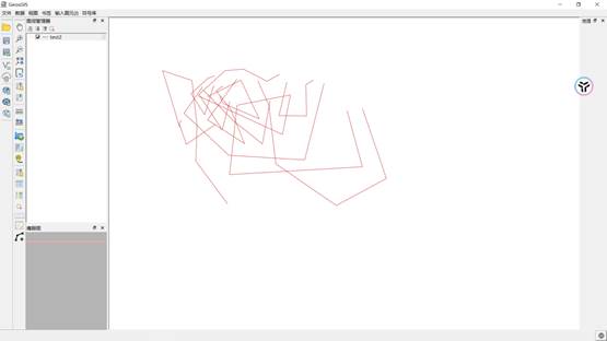
图 33 导入数据示意图
在图层列表中选中所需的图层,点击右侧边栏中的“启动/关闭几何编辑”按钮,启用编辑模式。接下来,点击“添加线”按钮,进入线添加模式。在这个模式下,使用鼠标左键在图框内的各个位置点击,以添加线的顶点。当线的形状满足需求后,通过右键停止添加顶点,并弹出窗口,用于设置新增线要素的属性值。
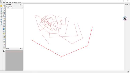
图 34 鼠标左键绘制新要素示意图
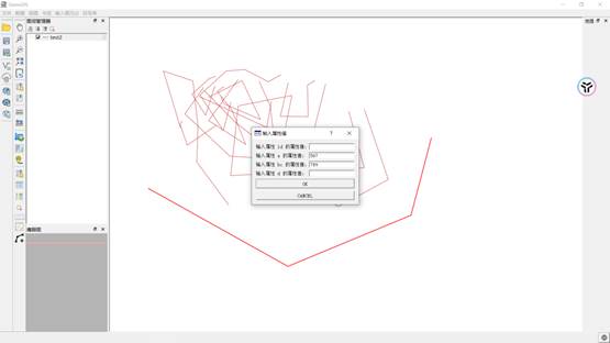
图 35 为新要素添加属性示意图
在属性值编辑窗口中,可以根据具体需求填写新增线要素的属性信息。这些属性值默认为Null,可以选择全部填入或者部分填入,具体取决于实际情况。如果想要取消添加,点击“Cancel”按钮即可。
添加操作完成后,新的线要素将在图层和属性表中显示。
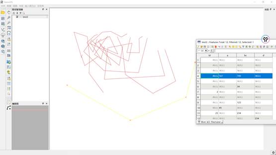
图 36 添加完成后的新要素及其属性展示
代码展示:
定义了一个名为QgsMapToolAddLine的类,继承自QgsMapTool,用于处理地图编辑操作。构造函数接受一个QgsMapCanvas和QgsVectorLayer,表示地图画布和当前图层。在canvasMoveEvent函数中,实时响应鼠标移动事件,根据用户的交互动作动态绘制线的顶点,对于左键点击,记录线的顶点坐标,并在右键点击时停止绘制,弹出窗口用于设置新增线要素的属性值。用户可以在弹出的属性值编辑窗口中填写相应的属性信息,完成后将新的线要素添加至图层。
整个过程通过QgsRubberBand类实现线的实时绘制,同时通过信号槽机制连接属性值编辑窗口的确认和取消按钮。在完成线要素的添加后刷新地图画布以更新显示。
QgsMapToolAddLine::QgsMapToolAddLine(QgsMapCanvas* canvas, QgsVectorLayer* currentlayer) :QgsMapTool(canvas), pMapCanvas(canvas), m_currentLayer(currentlayer)
{  pMapCanvas = canvas;  m_currentLayer = currentlayer;  //设置QgsRubberBand对象,绘制折线  pRubBand = new QgsRubberBand(pMapCanvas);  mColor = QColor(255, 0, 0);  LineWidth = 2;  ButtonClickFlag = false;
}  QgsMapToolAddLine::~QgsMapToolAddLine(void)
{  /*if(pRubBand){ delete pRubBand ; }*/
}
//重载鼠标移动事件
void QgsMapToolAddLine::canvasMoveEvent(QgsMapMouseEvent* e)
{  m_currentLayer->startEditing();  int xc, yc;  //如果鼠标左键没有双击  if (!ButtonClickFlag) {  return;  }  pRubBand->setColor(mColor);  pRubBand->setWidth(LineWidth);  xc = e->x();  yc = e->y();  //得到当前坐标变换对象  const QgsMapToPixel* pTransform = pMapCanvas->getCoordinateTransform();  //转换成地图坐标  QgsPoint mPoint(pTransform->toMapCoordinates(xc, yc));  if (pRubBand->numberOfVertices() > 1) {  pRubBand->removeLastPoint();  }  //把当前点添加到QgsRubberBand对象中用于绘制  pRubBand->addPoint(mPoint);
}
//重载鼠标单击事件
void  QgsMapToolAddLine::canvasPressEvent(QgsMapMouseEvent* e)
{  // 创建要素  QgsFeature feature;  int xc, yc;  pRubBand->setColor(mColor);  pRubBand->setWidth(LineWidth);  //得到当前坐标变换对象  const QgsMapToPixel* pTransform = pMapCanvas->getCoordinateTransform();  //得到产生事件的按钮信息  Qt::MouseButton mButton = e->button();  xc = e->x();  yc = e->y();  QgsPoint  mPoint(pTransform->toMapCoordinates(xc, yc));  //如果是左按钮  if (mButton == Qt::MouseButton::LeftButton) {  ButtonClickFlag = true;  //把当前点添加到QgsRubberBand对象中用于绘制  pRubBand->addPoint(mPoint);  mPointSet.append(mPoint);  }  else if (mButton == Qt::MouseButton::RightButton) {  pRubBand->addPoint(mPoint);  mPointSet.append(mPoint);  ButtonClickFlag = false;  //转化为几何体  QgsGeometry geometry = pRubBand->asGeometry();  feature.setGeometry(geometry);  if (feature.hasGeometry())  {  QgsFields fields = m_currentLayer->fields();  feature.setFields(fields);  QDialog inputDialog;  QFormLayout formLayout(&inputDialog);  QList<QString> attributeNames;  QList<QVariant> attributeValues;  for (const QgsField& field : fields)  {  QString attributeName = field.name();  QVariant::Type attributeType = field.type();  QString labelText = "输入属性 " + attributeName + " 的属性值:";  QString defaultValue = "";  // Set default value if needed  QLineEdit* inputLineEdit = new QLineEdit(&inputDialog);  inputLineEdit->setText(defaultValue);  formLayout.addRow(labelText, inputLineEdit);  attributeNames.append(attributeName);  }  QPushButton* okButton = new QPushButton("OK", &inputDialog);  QPushButton* cancelButton = new QPushButton("CANCEL", &inputDialog);  formLayout.addRow(okButton);  formLayout.addRow(cancelButton);  QObject::connect(okButton, &QPushButton::clicked, [&]() {  QMap<QString, QVariant> attributeMap;  for (int i = 0; i < attributeNames.size(); ++i)  {  QLineEdit* inputLineEdit = qobject_cast<QLineEdit*>(formLayout.itemAt(i, QFormLayout::FieldRole)->widget());  if (inputLineEdit)  {  QString inputValue = inputLineEdit->text().trimmed();  // Trim leading and trailing whitespaces  if (inputValue == "") continue;  QVariant::Type attributeType = fields[i].type();  QVariant convertedValue;  bool conversionOk;  switch (attributeType)  {  case QVariant::Int:  convertedValue = inputValue.toInt(&conversionOk);  break;  case QVariant::Double:  convertedValue = inputValue.toDouble(&conversionOk);  break;  // 其他类型的转换可以根据需要继续添加  default:  convertedValue = inputValue;  conversionOk = true;  }  if (!conversionOk)  {  // 用户取消输入,中断操作  return;  }  attributeMap[attributeNames[i]] = convertedValue;  }  }  QgsAttributes attributes;  for (const QString& attributeName : attributeNames)  {  QVariant value = attributeMap.value(attributeName, QVariant());  // Get value from map, default to QVariant()  attributes << value;  }  feature.setAttributes(attributes);  m_currentLayer->dataProvider()->addFeature(feature);  m_currentLayer->commitChanges();  pMapCanvas->refresh();  inputDialog.accept();  // Close the dialog after processing  });  QObject::connect(cancelButton, &QPushButton::clicked, [&]() {  pRubBand->reset();  mPointSet.clear();  inputDialog.reject();  // Close the dialog without processing  });  inputDialog.setWindowTitle("输入属性值");  inputDialog.exec();  pMapCanvas->refresh();  pRubBand->reset();  mPointSet.clear();  }  }  }
//设置绘制颜色和线宽
void QgsMapToolAddLine::SetColorAndWidth(QColor color, int nWidth)
{  mColor = color;  LineWidth = nWidth;
}  //返回构成线段的数据点数
int QgsMapToolAddLine::GetVertexCount()
{  return mPointSet.size();
}
//得到点的坐标
bool QgsMapToolAddLine::GetCoord(int index, double& x, double& y)
{  QgsPoint mPoint;  if (index >= mPointSet.size()) {  return true;  }  mPoint = mPointSet.at(index);  x = mPoint.x();  y = mPoint.y();
}
4.3 添加面要素
首先添加一个面数据之后,再点击按钮“添加面”
图 37 添加面按键
鼠标左键点击来绘制要素;
图 38 添加面操作
右键之后完成绘制,跳出相关属性的填写框;
图 39 输入属性
填写完之后,点击OK;完成绘制
图 40 添加面成功
相关代码思路分析:
首先,它获取当前在图层树视图中选中的图层,并把它转换为一个矢量图层(假设当前层是矢量层)。然后,该代码使该矢量图层进入编辑模式。接着,在地图画布中设置这个矢量图层为当前图层,并创建一个用于添加多边形要素的地图工具QgsMapToolAddFeature,最后将此工具设置为当前地图画布的工具,同时将捕获模式为多边形绘制。
代码部分如下:
void DataViewer::on_actionAddPolygons_triggered()
{    currentLayer = m_layerTreeView->currentLayer();    QgsVectorLayer* layer = qobject_cast<QgsVectorLayer*>(currentLayer);    //面编辑——添加要素    layer->startEditing();    m_mapCanvas->setLayers(QList<QgsMapLayer*>() << layer);    m_mapCanvas->setCurrentLayer(layer);    QgsMapToolAddFeature* addFeaturepolygonTool = new QgsMapToolAddFeature(m_mapCanvas, QgsMapToolCapture::CapturePolygon);    m_mapCanvas->setMapTool(addFeaturepolygonTool);    }